
High-speed indoor wireless chirp spread spectrum data link

a technology of spread spectrum and wireless chirp, which is applied in the field of high-speed indoor wireless chirp spread spectrum data link, can solve the problems of reducing the speed at which any signal processing has to operate, and the lengthening of the spread signal reduces so as to achieve simple hardware realization, prolong the duration, and reduce the speed at which any signal is processed

Inactive Publication Date: 2005-09-06
TELECOMM RES LAB
View PDF10 Cites 93 Cited by
  • Summary
  • Abstract
  • Description
  • Claims
  • Application Information

AI Technical Summary

Benefits of technology

[0007]In this invention, we propose the use of chirp signals (similar to those used by bats) to spread the bandwidth of the original data signal. There is a major difference between this technique and the conventional spread spectrum techniques used in indoor wireless communications, however, in that chirps spread the transmitted signal in both time and frequency rather than frequency alone. This means that the spread signal may have a longer duration than the original data symbol, despite the fact that the symbol rate remains the same. The overlap between adjacent symbols which results from this spreading is not a problem—chirps have a property called “time shift orthogonality” which allows two similar chirp signals to overlap in time provided they possess a small mutual time shift. The lengthening of the spread signals reduces the speed at which any signal processing has to operate as a result of the spread spectrum process. This results in a much simpler hardware realization despite its large occupied bandwidth.

Problems solved by technology

There is a major difference between this technique and the conventional spread spectrum techniques used in indoor wireless communications, however, in that chirps spread the transmitted signal in both time and frequency rather than frequency alone.
The lengthening of the spread signals reduces the speed at which any signal processing has to operate as a result of the spread spectrum process.

Method used


Image

  • High-speed indoor wireless chirp spread spectrum data link
  • High-speed indoor wireless chirp spread spectrum data link
  • High-speed indoor wireless chirp spread spectrum data link

Examples


Embodiment Construction

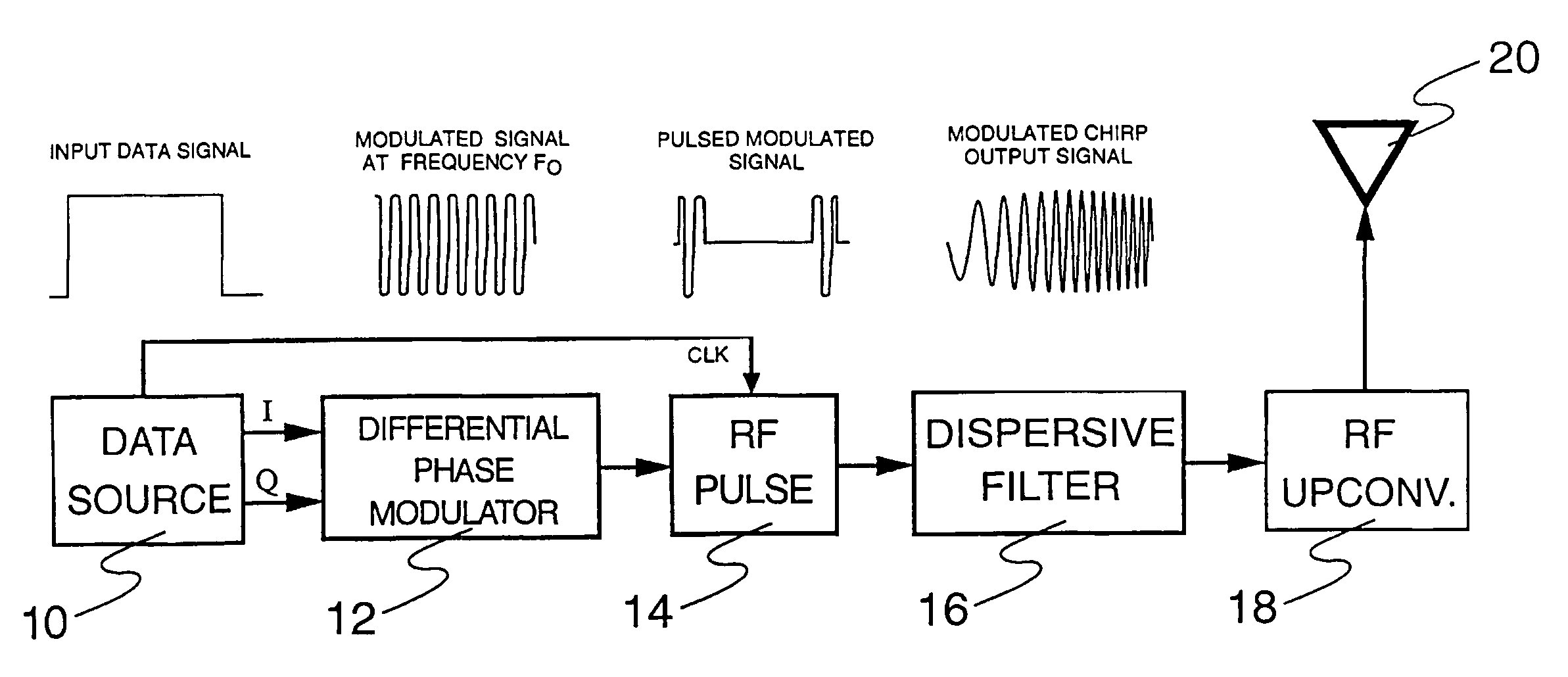
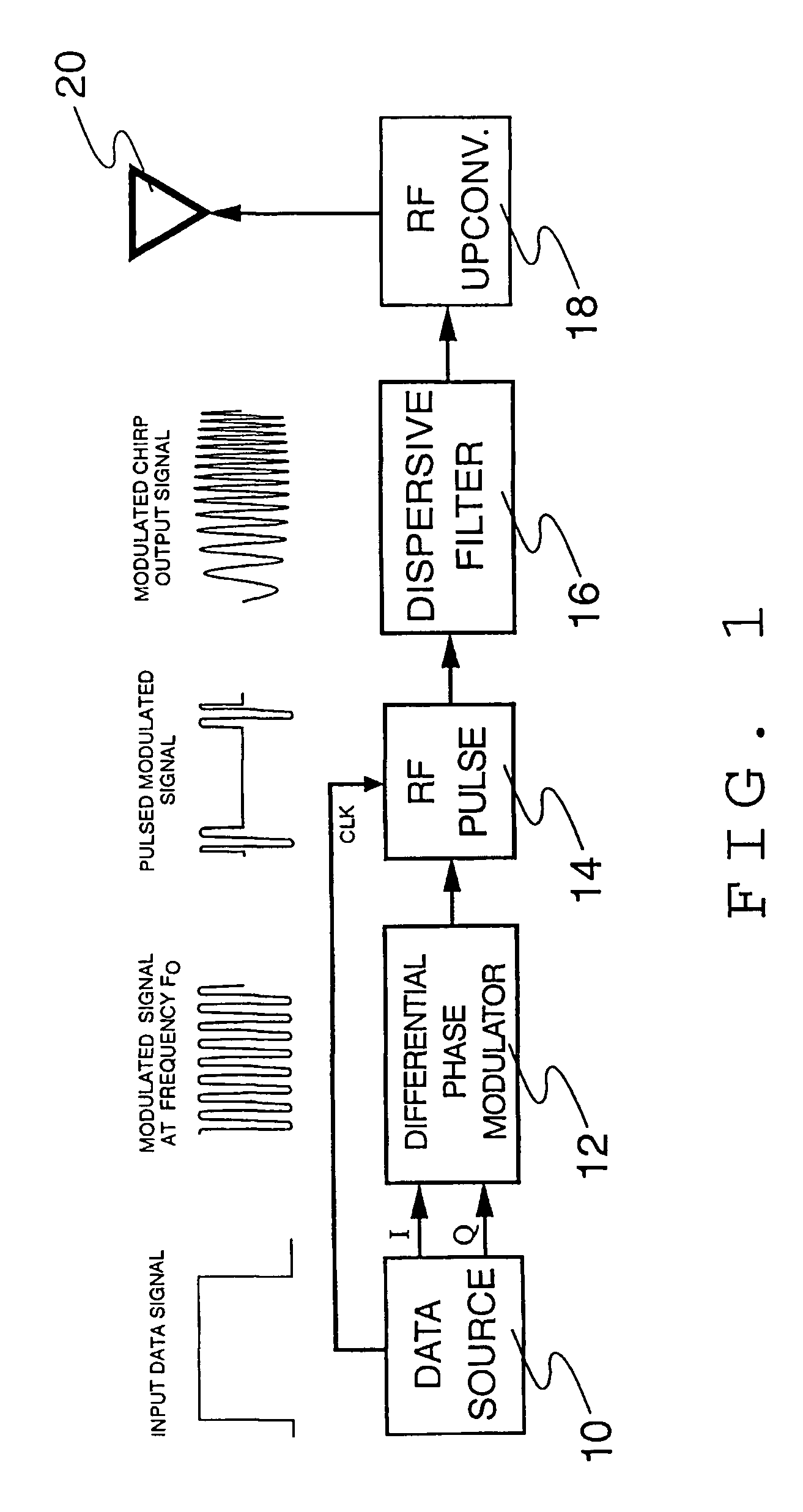
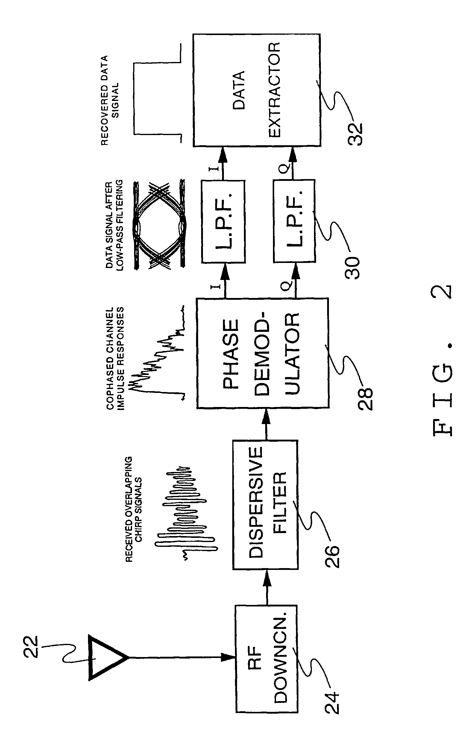
[0029]The basic apparatus which performs the operations described above consists of a transmitter (FIG. 1) and a receiver (FIG. 2). The transmitter's function is to modulate the data onto chirp signals and transmit these signals over the channel. The receiver's function is to recover the transmitted signal and reconstruct the original transmitted data. FIG. 6 and FIG. 7 show the transmitter and receiver schematics for the first enhanced version of the device, and FIG. 9 shows the receiver schematic for the second enhanced version of the device.

[0030]The schematic diagram of the basic transmitter is shown in FIG. 1. Also included in FIG. 1 are approximate plots of the signals at each stage of the device. Data from a data source 10 (which may be a computer or other digital information producing device) is fed into a differential phase modulator 12 which differentially encodes it onto a carrier. The encoding scheme should be a differential phase modulation scheme such as DPSK, DQPSK or...


PUM


Abstract

This invention modulates data onto a radio channel in such a way that the deleterious effects of the channel are reduced. This is accomplished in three steps: first, the information signal is modulated using a phase-differential modulation scheme. Second, the modulated signal is spread in both time and frequency by passing it through a dispersive filter, transmitting it through the channel, and removing the spreading using a dispersive filter in the receiver with the opposite characteristics of the filter in the transmitter. The third step, after demodulation, is to pass the signal through a low-pass filter to gather up the signal energy which has been dispersed by the channel. All three of these steps can be implemented with simple functional blocks, making this system very inexpensive to implement. Also included are two methods for enhancing the data throughput of the basic system, making it more bandwidth efficient.

Description

BACKGROUND OF THE INVENTION[0001]The reliable transmission of high data rate information through the short hop radio channel (i.e. a wireless channel having receiver-transmitter distance of less than 1 km) remains a complex and elusive engineering problem. The physical nature of the indoor radio channel causes random distortive effects that can render a communications system inoperable. The prior art includes many elaborate schemes that mitigate these effects, however they are generally very complex and unsuitable for applications requiring mobility and / or portability.[0002]Nature has already solved this problem, however, in the form of bats. Bats use echolocation for nighttime navigation and face many of the same distortion effects that radio systems do. Through the process of evolution they have developed powerful probing signals called chirps, which overcome many of these effects.[0003]The distortive effects referred to previously arise largely from the multipath nature of the ra...

Claims


Application Information

Patent Timeline
IPC IPC(8): H04B1/69
CPCH04B1/69H04B2001/6912
Inventor PINKNEY, JOHN A.NICHOLS, SPENCE T.
Owner TELECOMM RES LAB
Learn More