Gradient index rod lens unit and microchemical system having the same

a technology of microchemical systems and index rods, applied in the field of graded index rod lens units and microchemical systems having the same, can solve the problems of the limitation of the type of ions (glass components) that can be used, and the inability to obtain the desired value of chromatic aberration

Inactive Publication Date: 2005-09-06
NIPPON SHEET GLASS CO LTD
View PDF11 Cites 23 Cited by
  • Summary
  • Abstract
  • Description
  • Claims
  • Application Information

AI Technical Summary

Problems solved by technology

However, there is a limitation on the type of ions (glass components) that can be used to prepare a gradient index rod lens as described above.
For example, thallium, lithium, cesium, and silver are frequently used so that a desired value of chromatic aberration cannot be always obtained.
A lens having a predetermined range of chromatic aberration can be manufactured using each type of ion, but there can be a range of chromatic aberration between predetermined ranges of chromatic aberration, that cannot be obtained.
Therefore, in the case where measurements are carried out according to the photothermal conversion spectroscopic analysis method in a microchemical system as described above, there is a fear that the chromatic aberration of the gradient index rod lens can assume an unsuitable value depending upon the conditions, and hence measurements cannot be properly carried out.

Method used


Image

  • Gradient index rod lens unit and microchemical system having the same
  • Gradient index rod lens unit and microchemical system having the same
  • Gradient index rod lens unit and microchemical system having the same

Examples


first embodiment

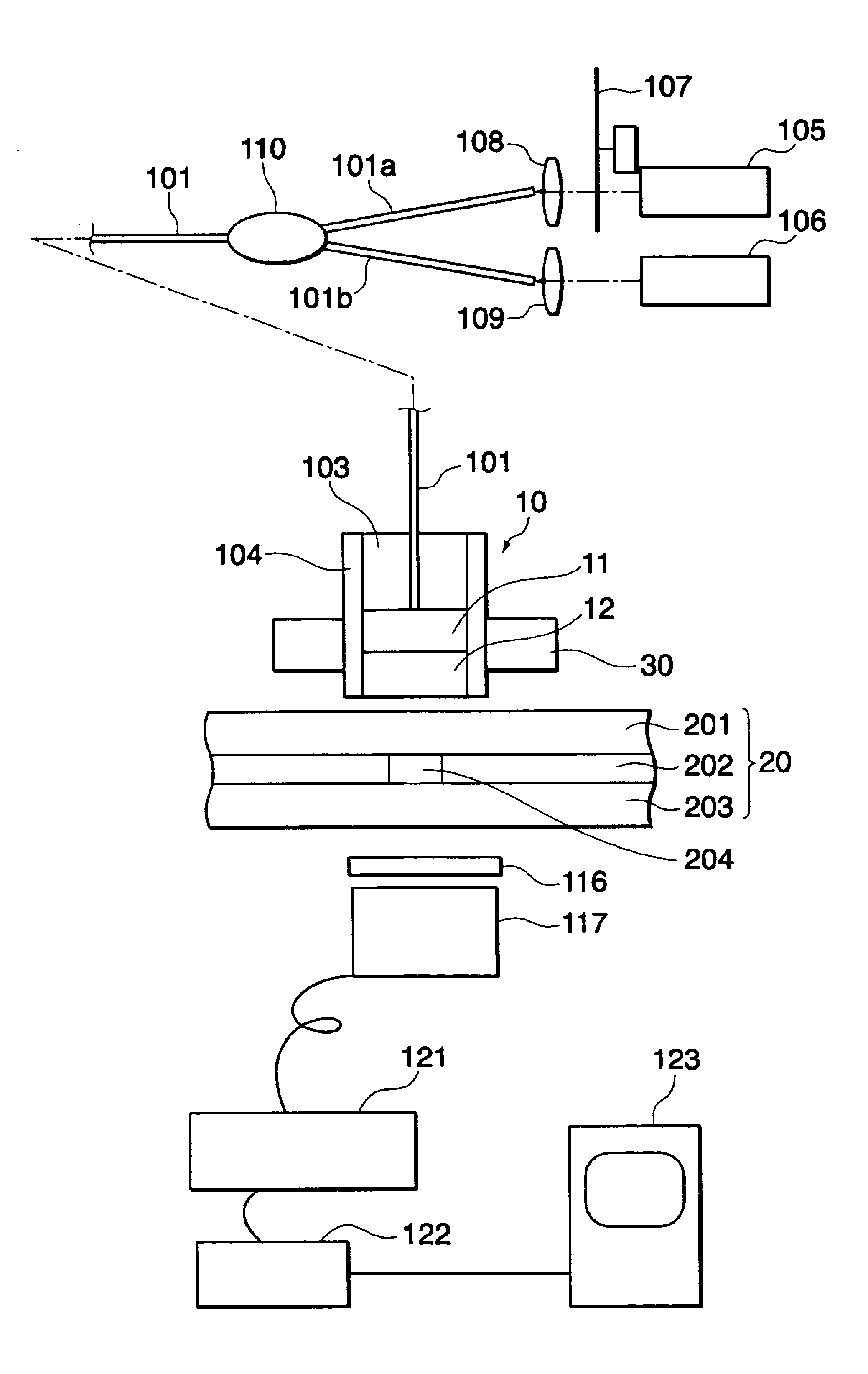
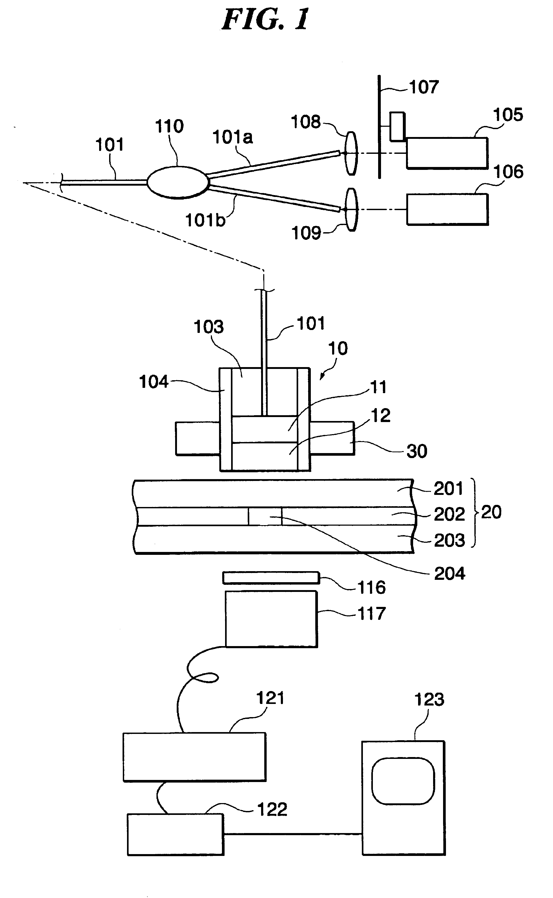
[0040]FIG. 1 is a schematic view showing the constitution of a microchemical system with a gradient index rod lens unit according to the present invention.

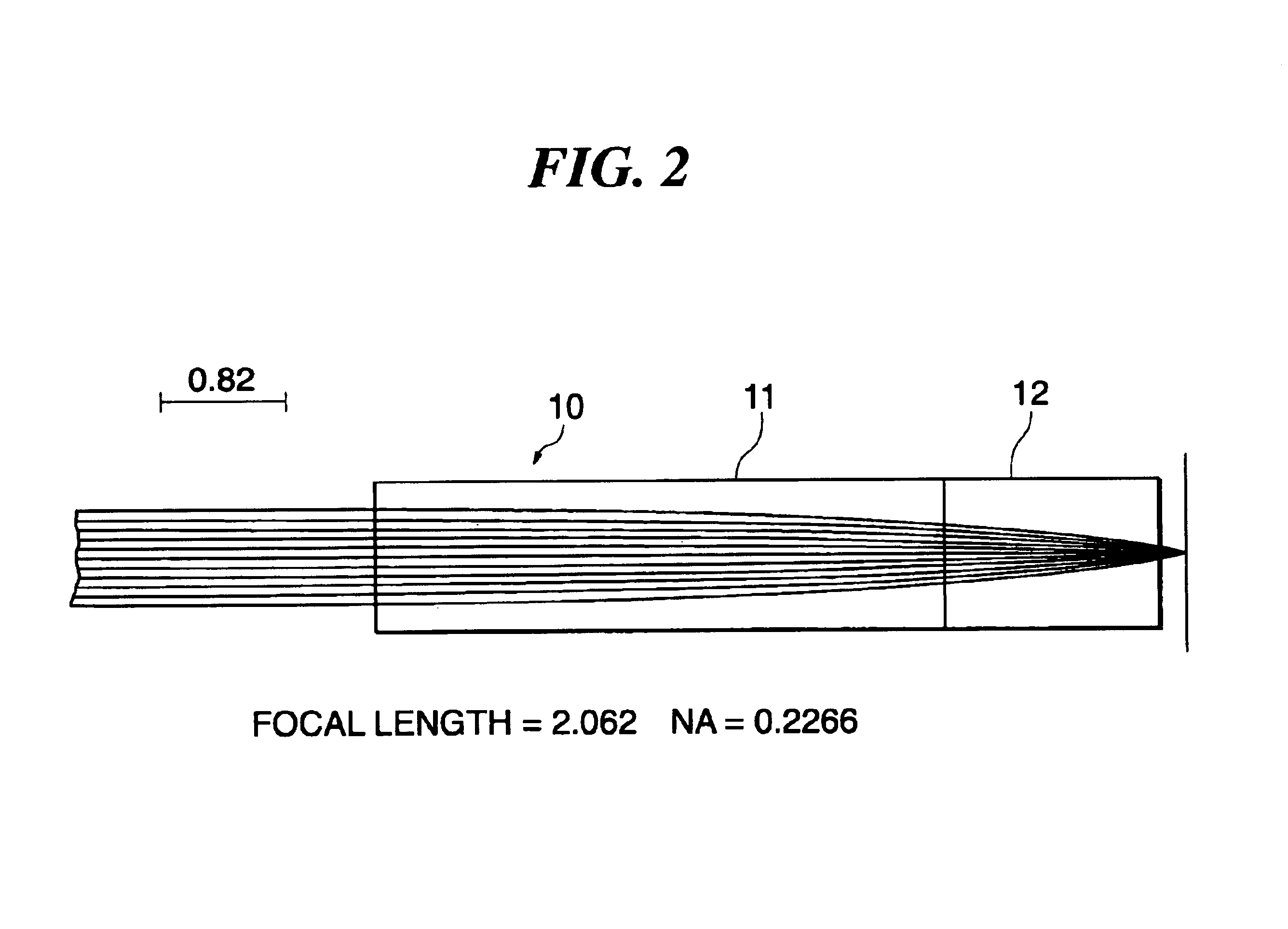
[0041]In FIG. 1, the gradient index rod lens unit 10 is comprised of two gradient index rod lenses 11 and 12 which have respective different chromatic aberrations. The gradient index rod lens 11 has a smaller chromatic aberration, and the gradient index rod lens 12 has a larger chromatic aberration. The gradient index rod lens 12 is different in the type of ions (glass component) from the gradient index rod lens 11 and thus has the larger chromatic aberration. The gradient index rod lenses 11 and 12 have end faces thereof bonded together by an organic adhesive agent or the like.

[0042]The gradient index rod lens unit 10 is mounted on a tip of an optical fiber 101 that transmits exciting light and detecting light in the single mode. The tip of the optical fiber 101 is mounted in a ferrule 103 that makes the outer diameter of the opt...

second embodiment

[0066]FIG. 4 is a schematic view showing the constitution of a microchemical system with a gradient index rod lens unit according to the present invention. In the figure, component elements corresponding to those in the microchemical system of FIG. 1 are designated by identical reference numerals, description of which is omitted.

[0067]In FIG. 4, the microchemical system according to the present embodiment is not provided with the optical fiber for guiding the exciting light and the detecting light, and instead, the exciting light and the detecting light are guided as space light to the gradient index rod lens unit 10. The exciting light output from the exciting light source 105 and the detecting light output from the detecting light source 106 are coaxially aligned with each other by a dichroic mirror 111. The coaxially aligned exciting light and detecting light are directed toward the gradient index rod lens unit 10. At this time, the optical path of the exciting light and the dete...


PUM

PropertyMeasurementUnit
diameteraaaaaaaaaa
aperture diameteraaaaaaaaaa

Abstract

There is provided a gradient index rod lens unit having a desired chromatic aberration. The gradient index rod lens unit is comprised of two gradient index rod lenses 11 and 12 with different chromatic aberrations and the entire lengths thereof adjusted, which are disposed in series with the optical axes thereof in alignment. The chromatic aberration of the gradient index rod lens unit can be set to a value falling within chromatic aberration ranges inherently possessed by the respective gradient index rod lenses 11 and 12.

Description

[0001]This application is a Continuation Application of International Application PCT / JP02 / 06843 filed Jul. 5, 2002, which claims the benefit of priority of JP 2001-209090 filed Jul. 10, 2001.TECHNICAL FIELD[0002]The present invention relates to a gradient index rod lens unit comprised of a plurality of gradient index rod lenses, and a microchemical system having the lens unit.BACKGROUND ART[0003]Conventionally, gradient index rod lenses are used in collimators for communication applications, optical coupling elements used in optical fibers, endoscope objective lenses for medical applications, objective lenses used in optical disk systems such as CD players and DVD players.[0004]Such a gradient index rod lens is made of a cylindrical transparent element which has a refractive index continuously varying from the center to the periphery thereof and which is known as a converging light-transmitting body for which the refractive index n(r) at a position a distance r from the central axi...

Claims


Application Information

Patent Timeline
Patent Type & Authority Patents(United States)
IPC IPC(8): G02B3/00G01N25/16G01N21/41G01N27/447G01N37/00G02B6/028
CPCG02B3/0087
Inventor YAMAGUCHI, JUNHATTORI, AKIHIKOKITAMORI, TAKEHIKO
Owner NIPPON SHEET GLASS CO LTD
Why Eureka
Try Eureka