Method for repairing generator rotor

a technology for generators and rotors, applied in the field of generator rotors, can solve the problems of increasing the cost and complexity of generator repair, stress-induced cracks may develop in the tooth tops of electrical generator rotors, and replacing generator retaining rings

Inactive Publication Date: 2005-09-13
SIEMENS ENERGY INC
View PDF11 Cites 15 Cited by
  • Summary
  • Abstract
  • Description
  • Claims
  • Application Information

AI Technical Summary

Benefits of technology

[0004]With the foregoing in mind, an improved generator rotor and a method of repairing existing generator rotors are provided. Improved generator rotors consistent with the present invention provide a tooth-top design that is more resistant to stress-induced cracking than conventional designs. Methods consistent with the present invention also provide techniques for repairing existing stress-damaged rotors to remove stress-induced cracks, without requiring new retaining rings.

Problems solved by technology

After prolonged use, stress-induced cracks may develop in the tooth tops of an electrical generator's rotor at locations near the ends of the rotor referred to as rotor-end sections.
Replacing a generator's retaining rings adds significant cost and complexity to the repair of a generator.

Method used


Image

  • Method for repairing generator rotor
  • Method for repairing generator rotor
  • Method for repairing generator rotor

Examples


Embodiment Construction

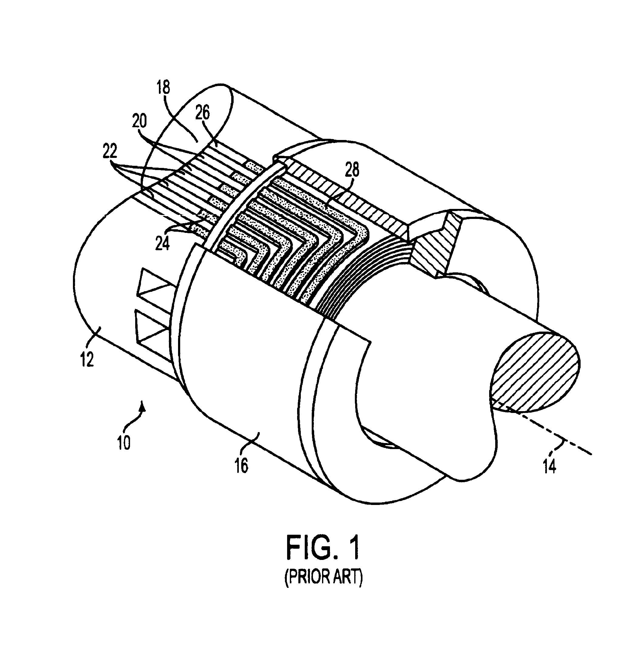
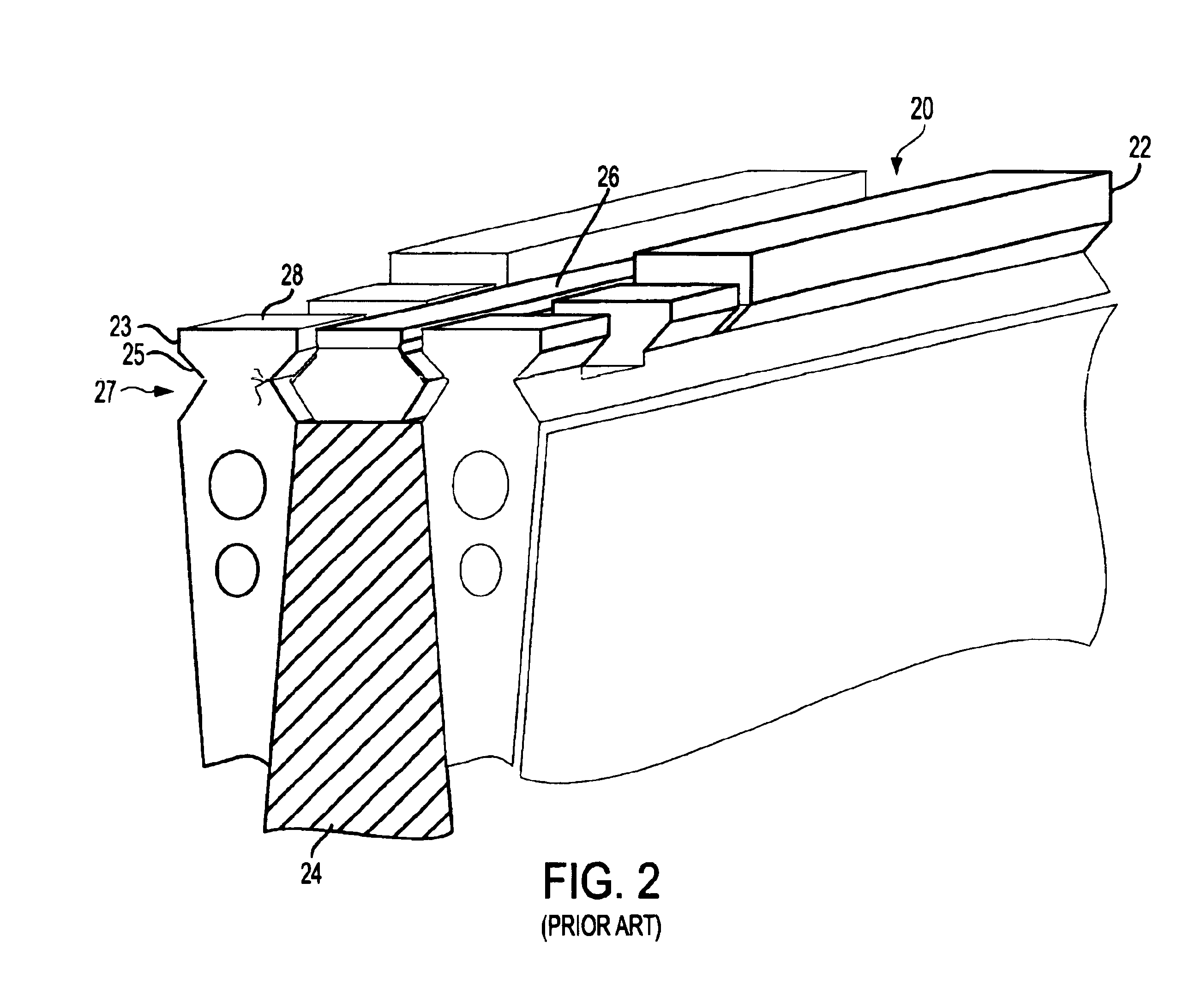
[0014]Electrical generators utilized in the power-generation industry typically include a rotor with two retaining-ring assemblies like the one illustrated in FIG. 1. The rotor assembly 10 includes a rotor 12, aligned for rotation about a longitudinal axis 14 and a retaining ring 16, installed on each end of the rotor 12. The rotor 12 includes a tooth region 18 with multiple longitudinal slots 20 defining a plurality of longitudinal teeth 22. Field windings 24 are disposed between the longitudinal teeth 22 and within the slots 20. The field windings 24 run the length of the rotor and make turns at each end of the rotor 12 to form end turns 28.

[0015]When the rotor assembly 10 is spinning, a radially-outward centrifugal force is exerted on the windings 24 and the end turns 28. In order to retain the field windings 24 tightly within the slots 20, wedges 26 are positioned in the openings of the slots 20. However, the end turns 28 extend beyond the rotor slots 20 and are not retained by ...


PUM

PropertyMeasurementUnit
outer diameteraaaaaaaaaa
depthaaaaaaaaaa

Abstract

An improved generator rotor (30) and a method of repairing an existing generator rotor (12) are disclosed. Methods consistent with the present invention provide techniques for repairing existing stress-damaged rotors (12) to remove stress-induced cracks (29), without requiring new retaining rings (16), to significantly extend the useful life of a generator without the cost and complexity of conventional repair techniques. Improved generator rotors (30) consistent with the present invention provide a tooth-top design that is more resistant to stress-induced cracking than conventional designs, resulting in new generators with longer useful lives.

Description

FIELD OF THE INVENTION[0001]The present invention relates generally to electrical generators, and more particularly to an improved generator rotor and a method of repairing existing generator rotors to eliminate stress-induced cracks.BACKGROUND[0002]After prolonged use, stress-induced cracks may develop in the tooth tops of an electrical generator's rotor at locations near the ends of the rotor referred to as rotor-end sections. A conventional approach to repairing such cracks is disclosed in U.S. Pat. No. 5,174,011 to Weigelt, which is incorporated by reference herein in its entirety. Weigelt discloses machining damaged teeth to remove large sections of stress-damaged material. The nature and extent of the machining disclosed in Weigelt makes it necessary to replace the generator's retaining rings. Replacing a generator's retaining rings adds significant cost and complexity to the repair of a generator.[0003]A new approach to refurbishing generators is needed that facilitates the r...

Claims


Application Information

Patent Timeline
Patent Type & Authority Patents(United States)
IPC IPC(8): H02K15/00
CPCH02K15/0006Y10T29/49728Y10T29/49011Y10T29/4973Y10T29/49725Y10T29/49012Y10T29/49726Y10T29/49009
Inventor ZHANG, JIPINGLIGHT, KEVINGARDNER, WILLIAM CANNONWHITENER, RANDY EDWARD
Owner SIEMENS ENERGY INC
Why Eureka
Try Eureka