
Screw capping head

Inactive Publication Date: 2005-09-13
KHS USA
View PDF47 Cites 24 Cited by
  • Summary
  • Abstract
  • Description
  • Claims
  • Application Information

AI Technical Summary

Benefits of technology

[0008]The typical capping head also requires seals such as o-rings and quad rings to prevent the environment and / or the product from entering and attacking the internal components of the capping head. The seals also prevent any lubrication in the capping head from escaping and contaminating the product being packaged. Failure of the seals often leads to a complete failure of the capping head. An erratic torque output also often results from worn or failed seals. To help prevent this from occurring, the capping heads require frequent maintenance to inspect and replace any worn seals and bearings.
[0015]In yet another embodiment, the invention provides a capping head without any conventional, resilient seals that require frequent replacement. Rather, a retainer positioned below the bearing includes an annular sidewall portion having a channel formed therein. The channel substantially prevents the liquid product from contaminating the bearing. Unlike a conventional resilient seal, however, the sidewall and channel of the metallic retainer do not wear over time. As a result, the magnetic clutch yields a more stable torque output for a longer period of time. To forego the use of conventional lubricants and resilient seals, while maintaining the bearing as the only conventionally lubricated component within the capping head, the other components that experience wear during normal operation can be coated to prolong their useful life. The coatings are applied directly to the wear surfaces of the respective components and will not contaminate the liquid product.

Problems solved by technology

Failure of the seals often leads to a complete failure of the capping head.
An erratic torque output also often results from worn or failed seals.
The relatively large inertial mass of the capping head plus the friction of the seals often produce erratic torque output through the magnetic clutch.
This approach has been helpful, but it has also been uneconomical and has unduly complicated and lengthened the changeover between packaging runs requiring two very different operating speeds.

Method used


Image

  • Screw capping head
  • Screw capping head
  • Screw capping head

Examples


Embodiment Construction

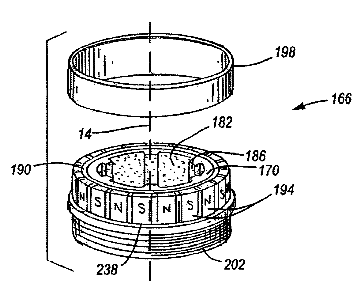
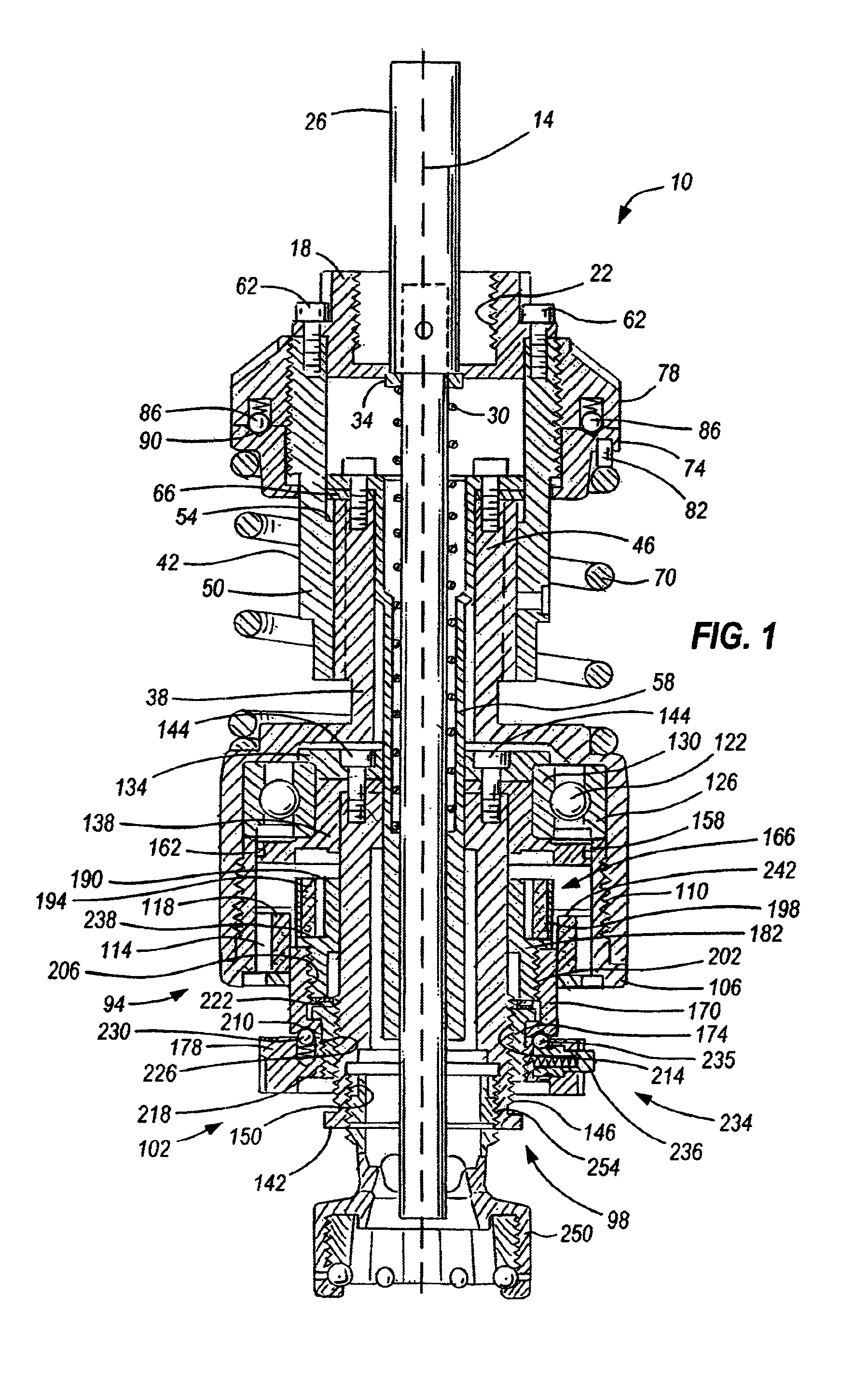
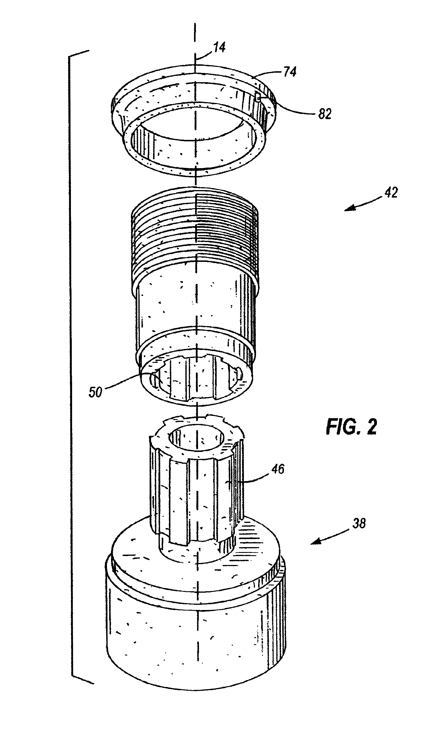
[0027]A screw capping headset, or capping head 10 embodying the present invention is shown in FIG. 1. The capping head 10 is rotatably driven along a longitudinal axis 14 by a machine spindle (not shown) of a capping machine (not shown). The machine spindle is secured to the screw capping head 10 via a spindle adapter 18. The spindle adapter 18 has internally formed threads 22 to secure the capping head 10 to the rotating spindle of the capping machine.

[0028]A knock-out rod 26 travels vertically through the capping head 10 to expel any unneeded or jammed closures (not shown) from the capping head 10. The knock-out rod 26 is biased towards an upper position by a compression spring 30. A spring retainer 34 axially aligns the spring 30 with respect to the knock-out rod 26 and is positioned between the knock-out rod 26 and the spring 30.

[0029]During operation, the knock-out rod 26 is actuated by the capping machine. When actuated, the knock-out rod 26 travels to a lower position where t...


PUM


Abstract

A screw capping head for use in a rotary capping machine includes a housing defining a longitudinal axis, a spindle rotatably carried by the housing, a first ring of magnets fixed within the housing, and a second ring of magnets coupled to the spindle for rotation with the spindle. The second ring of magnets is movable, without the use of tools, in the longitudinal direction with respect to both the spindle and the first ring of magnets to achieve a plurality of nested positions with respect to the first ring of magnets. The first and second rings of magnets define a magnetic torque coupling between the housing and the spindle, the strength of the torque coupling varying in a substantially linear relationship to the nested positions of the first and second rings of magnets.

Description

RELATED APPLICATIONS[0001]This application claims priority to U.S. Provisional Patent Application Ser. No. 60 / 296,560 filed on Jun. 7, 2001, which is incorporated herein by reference.FIELD OF THE INVENTION[0002]This invention relates generally to rotary capping machines, and more particularly to rotary capping machines that apply pre-threaded closures onto pre-threaded containers.BACKGROUND OF THE INVENTION[0003]Rotary capping machines for applying pre-threaded closures have been known for some time. To insure that a pre-threaded closure is not applied too loosely or too tightly and to insure product integrity, rotary capping machines are equipped with capping heads dependent upon a torque coupling. The torque coupling controls the application of torque to the closures to insure that they meet packaging specifications. Various types of torque couplings exist in the art such as mechanical clutches and magnetic clutches.[0004]A magnetic clutch typically consists of axially-opposed rin...

Claims


Application Information

Patent Timeline
IPC IPC(8): B65B7/28B67B3/20B67B3/00
CPCB65B7/2835B67B3/2066B67B3/2086B67B3/268
Inventor ARRANT, MARK A.KIESLING, RONALD A.
Owner KHS USA
Learn More