Circular Superimposed Magnetic Circuit Switched Reluctance DC Motor

A DC motor, switched reluctance technology, applied in the direction of synchronous machine parts, etc., can solve the problems of wasting materials, increasing production costs, unsatisfactory running stability, etc., to achieve simple manufacturing, reduced production costs, and improved power density Effect

Active Publication Date: 2018-07-27
冯西川
View PDF8 Cites 0 Cited by
  • Summary
  • Abstract
  • Description
  • Claims
  • Application Information

AI Technical Summary

Problems solved by technology

As a result, the working efficiency, power density, and running stability of the motor are not ideal, and at the same time waste materials and increase production costs

Method used


Image

  • Circular Superimposed Magnetic Circuit Switched Reluctance DC Motor
  • Circular Superimposed Magnetic Circuit Switched Reluctance DC Motor
  • Circular Superimposed Magnetic Circuit Switched Reluctance DC Motor

Examples


Embodiment 1

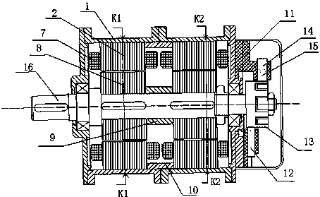
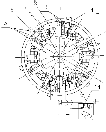
[0029] Such as Figure 1-6 As shown, the present invention includes a stator unit and a rotor unit installed in the stator unit, and the stator unit includes a plurality of split stator core laminations 2 installed in the casing 1, wound on the stator core laminations 2 protruding The stator winding 7 on the pole, the stator permanent magnet 3 and the ferrous magnetic conduction wedge assembly fixing the stator core lamination 2 and the stator permanent magnet 3, and the two ends of each independent stator core lamination 2 are placed on the surface Stator permanent magnets 3 of the same polarity, stator core laminations 2 and stator permanent magnets 3 form a unipolar stator core lamination unit, all stator core laminations on the stator unit 2 stator windings on salient poles 7 A-phase stator windings and B-phase stator windings are connected at intervals; the rotor unit includes rotor laminations 8 for driving the shaft 16 to rotate.

[0030] The casing is made of aluminum...

Embodiment 2

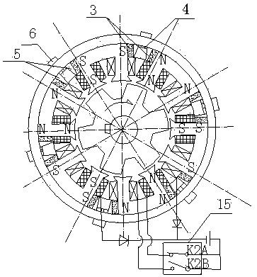
[0033]This embodiment is preferably as follows on the basis of the above-mentioned embodiment 1: the stator unit and the rotor unit are at least 2 and the number is equal, and the number of the stator unit is N and connected in series on the shaft 16, wherein the value range of N is A natural number between 2-4. In this embodiment, the number of groups of the stator unit and the rotor unit is 2 groups, and the two groups of stator units are respectively K1 and K2. The number of sets of the stator unit and the rotor unit can also be adjusted according to actual needs, and the use is more flexible. With the design of multiple independently working stator units and multiple groups of independently working rotor units, individual units can be designed and manufactured separately during design and manufacture, making the manufacturing easier, the manufacturing process optimized, and the production cost more reasonable.

Embodiment 3

[0035] This embodiment is preferably as follows on the basis of the above-mentioned embodiments: adjacent two groups of rotor units are staggered by 1 / N salient pole pitches in the circumferential distribution positions of the respective salient poles. In order to overcome the torque ripple generated when the A-phase stator winding and the B-phase stator winding commutate, that is, when the K1 rotor unit is at the commutation zero torque position, the K2 rotor unit is at the torque peak position, making the torque output more stable.


PUM


Abstract

The invention discloses a loop superposition magnetic circuit switch reluctance direct current motor. The motor comprises a stator unit and a rotor unit arranged in the stator unit. The stator unit comprises a number of split stator iron core laminations arranged in a cabinet, stator windings wound on the salient poles of the stator iron core laminations, stator permanent magnets, and an iron-magnetically permeable wedge assembly used for fixing the stator iron core laminations and the stator permanent magnets. A stator permanent magnet of the same polarity is placed on the ring direction surface of both ends of each independent stator iron core lamination. A stator iron core lamination and a stator permanent magnet form a unipolar stator iron core lamination single body. After a stator winding on the salient pole of a stator iron core lamination is energized, an electromagnetic field generated by the winding of the phase and a permanent magnetic field are superimposed, strengthened and applied on the rotor. The rotor is in a non-winding non-magnet salient pole type structure. The loop superposition magnetic circuit switch reluctance direct current motor provided by the invention uses the structure, and has the advantages of high work efficiency, low power consumption, high power density, smooth operation and excellent comprehensive performance.

Description

technical field [0001] The invention relates to the field of switched reluctance motors, in particular to a switched reluctance direct current motor with a circumferentially superimposed magnetic circuit. Background technique [0002] The existing switched reluctance motor stator and rotor are salient pole structures, the stator salient poles have independent windings, the rotor salient poles have neither windings nor permanent magnets, and the number of rotor salient poles is two less than the number of stator salient poles. When the salient poles of the rotor and a certain salient pole of the stator are close to the magnetic field axis, the switch is controlled by the position sensor to close, and the relevant salient pole windings of the stator are energized to generate a magnetic field and form a magnetic circuit with the relevant salient poles of the rotor. According to the principle of minimum reluctance, the suction torque is generated between the relevant stator and ...

Claims


Application Information

Patent Timeline
Patent Type & Authority Patents(China)
IPC IPC(8): H02K21/04
CPCH02K21/04
Inventor 冯西川
Owner 冯西川
Why Eureka
Try Eureka