
Rotor position fault identification and compensation method based on aviation three-level motor starting/power generation control system

A technology for rotor position and power generation control, which is used in motor generator/starter, estimation/correction of motor parameters, starter of a single polyphase induction motor, etc. Harmonics, burning power inverter bridge and other problems, to achieve stable torque output and speed-up start, to meet the tracking control stability and timeliness effects

Pending Publication Date: 2021-12-21
SHAANXI AVIATION ELECTRICAL
View PDF0 Cites 0 Cited by
  • Summary
  • Abstract
  • Description
  • Claims
  • Application Information

AI Technical Summary

Problems solved by technology

During the starting process of the controller, due to the complex internal structure of the starting controller, during the starting process, the harmonic signals of various frequency bands generated by various power loops, digital signal loops, and analog level signal loops are used to collect and output the rotor position. The signal interferes, which causes the rotor position to be read incorrectly, causing a sudden change in the inverter armature current during motor start control, resulting in a sudden change in the output torque of the motor; in severe cases, the excessive current causes the power inverter bridge to be burned, and finally causes the motor to start. fail
[0003] At present, in the starting control of aeronautical motors, hardware filter circuits are mostly used to filter the signals collected by the resolver decoding chip to solve the problem of resolver acquisition interference. A complex and difficult-to-analyze frequency band or amplitude glitch harmonic, which makes it difficult for the hardware filter circuit to remove the glitch harmonic, and there is still resolver interference
At present, most of the starting control software deal with the presence of resolver interference by further filtering through algorithms, or performing fault alarms according to the LOT and DOS modes in the resolver decoding chip. This processing method cannot be completely used in actual use Realization: within the set time period, and in the case of resolver interference, the need to ensure the normal starting function of the motor through software algorithms

Method used


Image

  • Rotor position fault identification and compensation method based on aviation three-level motor starting/power generation control system
  • Rotor position fault identification and compensation method based on aviation three-level motor starting/power generation control system
  • Rotor position fault identification and compensation method based on aviation three-level motor starting/power generation control system

Examples


Embodiment Construction

[0019] Embodiments of the present invention are described in detail below, and the embodiments are exemplary and intended to explain the present invention, but should not be construed as limiting the present invention.

[0020] The present invention provides a motor rotor position fault identification and compensation method suitable for aviation starter / power generation controllers. The calculation method includes two parts: rotor position fault identification and rotor position compensation. The specific algorithm principle is as follows:

[0021] The calculation formula of aviation three-stage synchronous motor speed is as follows:

[0022] n=60f / n p (1)

[0023] Among them, n is the mechanical speed of the motor, f is the frequency corresponding to the electrical angle, and n p is the number of pole pairs of the motor.

[0024] The electrical angular frequency of the main generator of the synchronous motor and the electrical angle variation formula of the rotor positio...


PUM


Abstract

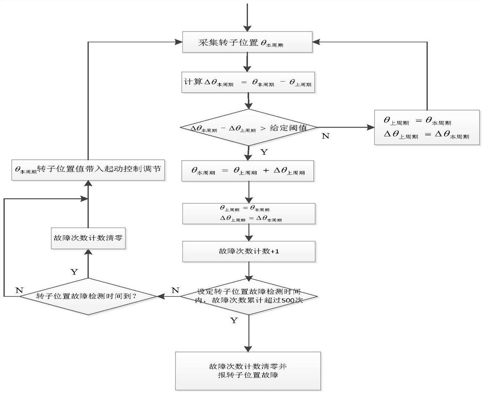
The invention provides a rotor position fault identification and compensation method based on an aviation three-level motor starting / power generation control system. The method comprises the steps of: firstly calculating a rotor position variable quantity in each sampling interval through using a collected rotor position; using a difference value between the rotor position variable quantity of the current period and the rotor position variable quantity of the previous period, namely delta theta<current period>-delta theta<previous period>, as a rotor position sampling fault judgment condition; when the delta theta<current period>-delta theta<previous period> is greater than a set threshold value, performing rotor position compensation and performing fault counting; and when the fault count exceeds a set number of times within the given time, reporting rotor position sampling faults, and stopping startup. According to the rotor position fault identification and compensation method, the rotor position can be continuously compensated under the condition that a rotor position sampling error occurs in a continuous period of time under the condition that a rotary transformer is disturbed, so that stable torque output and acceleration starting of the motor are ensured, and the tracking control stability and timeliness of a servo control system are met.

Description

technical field [0001] The invention belongs to the technical field of rotor position identification of aviation three-stage motors, and relates to a motor rotor position fault identification and compensation method suitable for aviation starting / generating controllers. Background technique [0002] The starting / generating control system (SGCU for short) utilizes the motor / generating reversible principle of the aviation three-stage synchronous motor to realize the time-sharing multiplexing function of starting and generating. Before the engine is ignited, it acts as a starter to drive the engine to accelerate to the ignition speed, and the engine injects fuel to ignite. When the engine runs independently, it in turn drives the starter generator to enter the power generation state, and converts the mechanical energy of the engine into electrical energy to meet the needs of the aircraft. The power supply requirements of the system are met, so as to achieve the purpose of one m...

Claims


Application Information

Patent Timeline
Patent Type & Authority Applications(China)
IPC IPC(8): H02P23/14H02P1/26
CPCH02P23/14H02P1/26
Inventor 宋超李思齐杜东泉熊春兰
Owner SHAANXI AVIATION ELECTRICAL
Learn More