Liquid filling system with improved set-up and fill weight calibration/verification capabilities

a filling system and filling weight technology, applied in liquid handling, packaging goods types, liquid handling, etc., can solve the problems of affecting the overall production capability of either type of system, automatic or semi-automatic, affecting the accuracy of filling, so as to improve the overall system safety, minimize, if not eliminate, the potential for operator error

Inactive Publication Date: 2005-09-13
ROSEN ROBERT A
View PDF4 Cites 29 Cited by
  • Summary
  • Abstract
  • Description
  • Claims
  • Application Information

AI Technical Summary

Benefits of technology

[0056]It is yet another object of the present invention to provide an improved metering device calibration / set-up system that automatically corrects the output per fill cycle of one or more metering devices when an out-of-specification situation is detected.
[0057]It is still another object of the present invention to provide an improved metering device calibration / set-up system that improves overall system safety by allowing the calibration / set-up process to be completed without operator intervention or the need to bypass the guard assembly.
[0058]It is a further object of the present invention to provide an improved metering device calibration / set-up system that minimizes, if not eliminates, the potential for operator error during the calibration / set-up process for a liquid filling system.
[0059]It is another object of the present invention to provide an improved filling nozle configuration for greater control and accuracy.

Problems solved by technology

The overall production capability of either type of system, automatic or semi-automatic, is compromised by the amount of “downtime” required for cleaning, calibration / set-up, and periodic maintenance.
The liquid metering devices sit idle during the entire container indexing process and for part of the time that the nozzles are in motion.
As the number of filling stations increases in either the automated or semi-automated systems described above, additional design goals and challenges arise.
In general, a significant amount of “downtime” is required to clean filling machinery when changing from one product to another (see the detailed discussion of cleaning processes below).
While a system 40 of this type is generally recognized as being more complex and costly than an in-line walking beam system, it does possess the ability to achieve higher overall production rates.
Unfortunately, both of the prior art continuous-motion filling processes described above possess certain shortcomings.
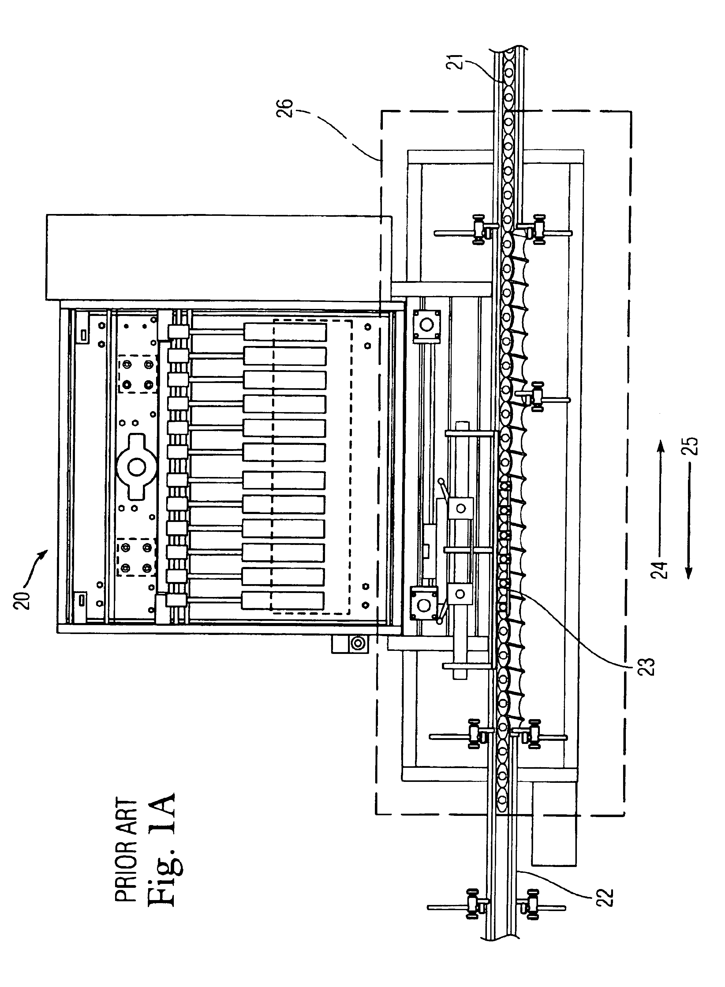
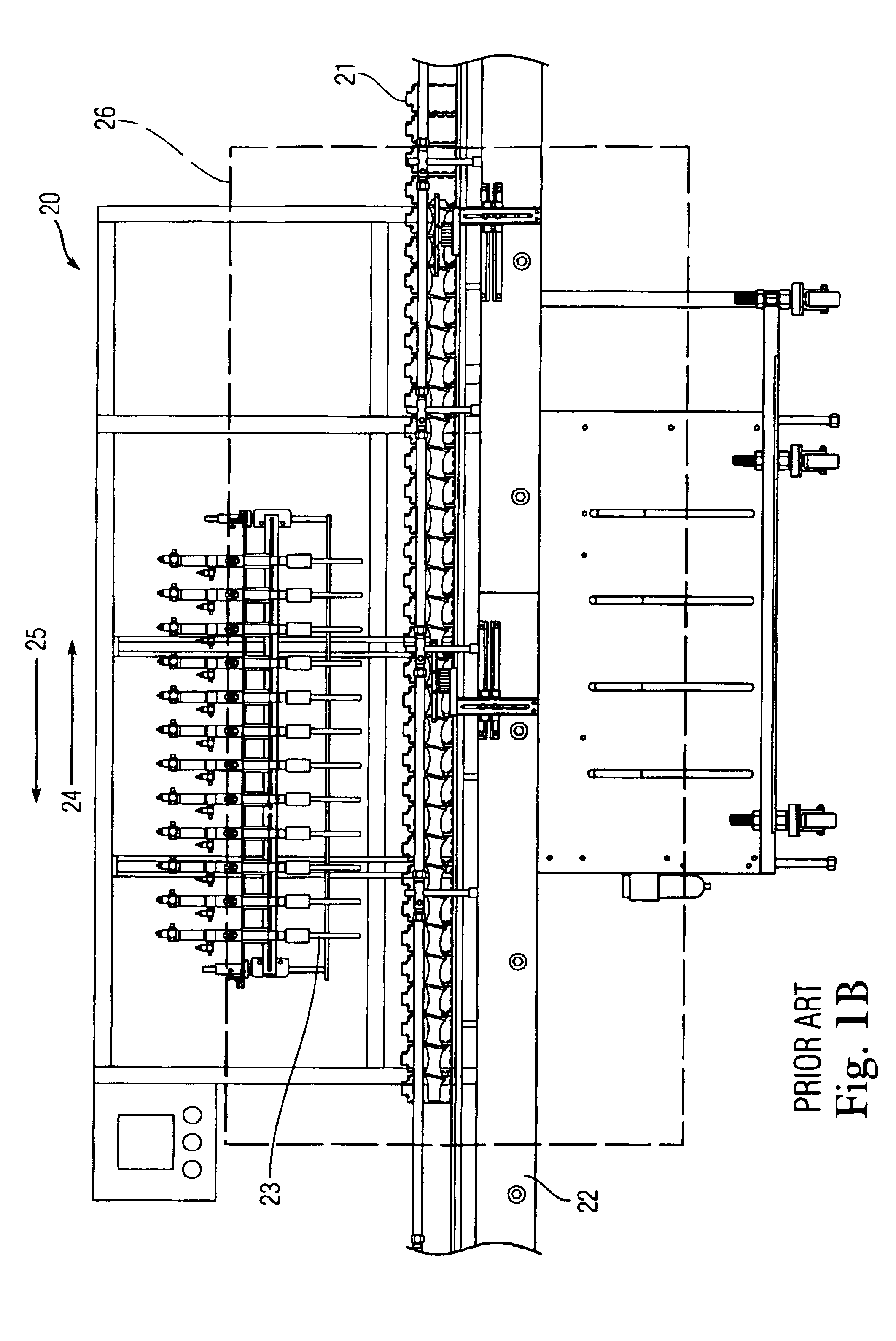
In-line, walking beam systems utilizing single-lane conveyors possess overall production rate limitations that are practical functions of the physical size of the walking beam assembly and the length / distance of its travel during the filling process.
This limitation is imposed by the need for the bank of nozzles to return to the infeed end of the filling zone in order to begin filling the next set of empty containers, and results in maximum overall production rate capabilities that fall far short of those possible with rotary filling systems.
On the other hand, rotary systems are generally more complex in design and construction than in-line walking beam systems.
In addition, the changeover process between production runs associated with a rotary system is more time consuming and costly in terms of both actual and opportunity costs.
The cleaning process, while known to be of a time consuming nature, is acknowledged as a “necessary evil” in order to avoid potentially hazardous problems with cross-contamination between products / batches.
The primary detriment associated with the use of a CIP process is the “opportunity cost” associated with not being able to operate the filling system in its production mode while the product contact parts are being subjected to the cleaning cycle.
The disassembly / cleaning / re-assembly process is labor intensive and subjects the individuals involved to potentially hazardous products, cleaning fluids, or the combinations thereof.
However, there are very few situations where the combination of cost and floor space required by two, separate and complete filling systems makes for a profitable production environment.
In today's business environment of minimal inventories and “just in time” manufacturing, it is simply not economically feasible to dedicate an entire liquid filling system to a single product.
Again with respect to factor (4) above, the calibration and / or set-up of the metering devices (i.e. pumps) in a production environment liquid filling system can also be a time consuming, labor intensive process.
In any of the manual processes discussed above, the possibility of operator error exists.
Examples of potential operator error include (1) the failure to properly position a nozzle over the collection receptacle during the priming / air purging process, (2) the entering of an incorrect gross adjustment set point at the start of the filling cycle calibration process, (3) making an incorrect association between a net fill weight and the fill station that generated it (and subsequent fine tuning adjustment of the wrong fill station) during either the filling cycle calibration or the fill weight verification process, and (4) the misreading or miscalculation of otherwise correct fill weights leading to unnecessary fine tuning adjustments during either the filling cycle calibration or the fill weight verification process.
In addition to the actual costs, outlined above in terms of manual labor and product waste (e.g. inaccurate fills resulting from air in the intake or discharge lines, the iterative process used to establish proper fill volumes, operator error), the calibration / set-up process also carries the “opportunity cost” associated with not being able to operate the liquid filling system in its production mode while the calibration / set-up process is ongoing.
Obviously, the more time required to complete a manual calibration / set-up process, the greater the associated opportunity cost.

Method used


Image

  • Liquid filling system with improved set-up and fill weight calibration/verification capabilities
  • Liquid filling system with improved set-up and fill weight calibration/verification capabilities
  • Liquid filling system with improved set-up and fill weight calibration/verification capabilities

Examples


Embodiment Construction

[0115]FIG. 3 shows a top perspective view of a liquid filling system 10 according to a first embodiment of the present invention, including a container handling subsystem 102, a nozzle support subsystem 104, a product contact subsystem 106, and a controls / utilities subsystem 108.

[0116]The container handling subsystem 102 carries the containers 100 to and from the filling area and, while they are in the filling area, positions them for the entry of the filling nozzles 154.

[0117]The nozzle support subsystem 104 articulates the nozzles 154, moving them up and down (or, into and out of the containers 100) during the filling process. In addition, as will be described, nozzle support subsystem 104 may employ an intermittent-motion filling process by which the nozzles 154 are moved back and forth from container-to-container, or a continuous motion process by which nozzles 154 track the moving containers along the filling area.

[0118]The product contact subsystem 106 contains the elements of...


PUM

PropertyMeasurementUnit
angleaaaaaaaaaa
power ratingaaaaaaaaaa

Abstract

An improved method and apparatus for a liquid filling system is herein disclosed incorporating means for generating greater overall production rate efficiencies (i.e. number of filled containers per minute per filling station) for automatic systems utilizing diverter valve and/or walking beam (i.e. continuous-motion) filling technologies with, for example, non-traditional ratios between the number of filling stations and the number of filling nozzles. The methods/apparatus disclosed herein also incorporate means to more efficiently changeover and clean up, in either a clean-in-place (CIP) or clean-out-of-place (COP) configuration, the product contact parts that become “dirty” when used in a production environment. Finally, an improved method and apparatus designed to provide a means for priming and air purging the product contact path of liquid filling machinery, a fill volume calibration procedure, and a fill weight verification cycle is also herein described.

Description

CROSS-REFERENCE TO RELATED APPLICATIONS[0001]This application is a division of U.S. patent application Ser. No. 10 / 011,963, filed Nov. 5, 2001, now U.S. Pat. No. 6,761,191, entitled “Liquid Filling System with Improved Fluid Displacement, Nozzle and Container Handling, Cleaning, and Calibration / Set-up Capabilities”.[0002]U.S. application Ser. No. 10 / 011,963 derives priority from, and is commonly assigned with, the following provisional applications:[0003](1) Ser. No. 60 / 245,300, filed Nov. 3, 2000, entitled “Clean-Out-of-Place (COP) Liquid Filling System”;[0004](2) Ser. No. 60 / 267,927, filed Feb. 12, 2001, entitled “Liquid Filling System with Diverter Valve”;[0005](3) Ser. No. 60 / 268,521, filed Feb. 14, 2001, entitled “Clean-In-Place (CIP) Liquid Filling System”;[0006](4) Ser. No. 60 / 316,528, filed Aug. 31, 2001, entitled “Dual-Lane Walking Beam Liquid Filling System”; and[0007](5) Ser. No. 60 / 316,536, filed Aug. 31, 2001, entitled “System to Automate the Set-up, Calibration, and Fi...

Claims


Application Information

Patent Timeline
Patent Type & Authority Patents(United States)
IPC IPC(8): B67C3/24B67C3/02B67C3/00B67C3/20
CPCB67C3/001B67C3/005B67C3/02B67C3/20B67C3/24
Inventor ROSEN, ROBERT A.
Owner ROSEN ROBERT A
Why Eureka
Try Eureka