In-wheel motor for electric automobiles

a technology for electric automobiles and in-wheel motors, which is applied in the direction of electric devices, magnetic circuit rotating parts, magnetic circuit shapes/forms/construction, etc., can solve the problems of narrow selection range, affecting convenience of use, and raising design difficulties

Inactive Publication Date: 2005-09-13
JAPAN SCI & TECH CORP
View PDF17 Cites 40 Cited by
  • Summary
  • Abstract
  • Description
  • Claims
  • Application Information

AI Technical Summary

Benefits of technology

[0042]Through change in the gear ratio of the planetary gear mechanism of the reduction gear mechan...

Problems solved by technology

Thus, when existing in-wheel motors designed for certain vehicles are to be applied to another vehicle, an applicable in-wheel motor is limited to that having a specific mounting section; i.e., a mounting section that satisfies a specific positional relation between the mounting section and a wheel.
Therefore, an in-wheel motor has been...

Method used


Image

  • In-wheel motor for electric automobiles
  • In-wheel motor for electric automobiles
  • In-wheel motor for electric automobiles

Examples


Embodiment Construction

[0048]Modes for carrying out the present invention will next be described with reference to the drawings.

[0049]Embodiments of the present invention will next be described with reference to the following drawings.

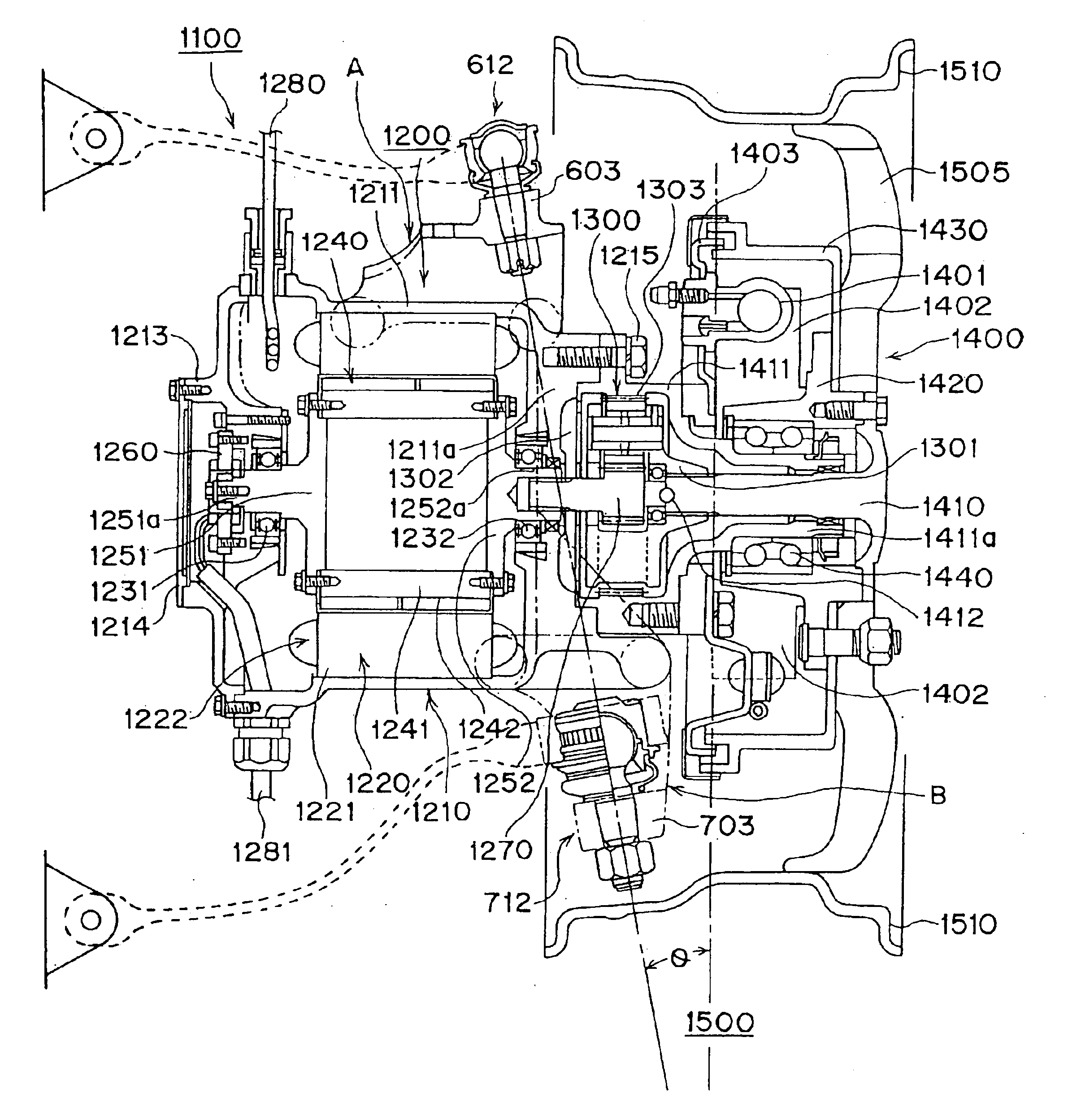
[0050]FIG. 4 exemplifies an in-wheel motor of the present invention and means for mounting the in-wheel motor while other structural features are omitted. FIG. 5 is a longitudinal sectional view of the in-wheel motor according to the present invention.

[0051]First, the in-wheel motor of the present invention, particularly the inner structure thereof, will be described with reference to FIGS. 4 and 5.

[0052]A drive motor 1200 in a drive mechanism 1100 is a permanent-magnet-type AC motor, particularly a 6-phase synchronous AC motor. A casing 1210 of the drive motor 1200 includes an outer frame 1211, an end ring 1213, and an end plate 1214. The outer frame 1211 is cylindrical and includes a bracket portion 1211a, which is located at the right-hand side thereof in FIG. 5. A stator...


PUM


Abstract

The present invention provides an in-wheel motor for an electric vehicle allowing a drive motor to be freely mounted onto a chassis irrespective of the shape, structure, and characteristics of the drive motor as well as allowing free selection of a reduction gear ratio without need to replace a drive motor.
An in-wheel motor for an electric vehicle includes a drive motor (1200), a reduction gear mechanism (1300), a wheel bearing, and a mechanical brake and serves as a drive apparatus for an electric vehicle. The drive motor (1200) includes a casing (1210) which houses a rotor (1240) and a stator (1220); the reduction gear mechanism (1300) is implemented by a planetary gear mechanism; a wheel bearing is fixedly attached to the outer circumference of an end portion of a housing (1411), which houses a wheel shaft (1410) coupled to an output element of the planetary gear mechanism; mounting blocks (800, 810) having engagement means are provided respectively at upper and lower outside portions of the casing (1210); and attachments are attached to the corresponding mounting blocks (800, 810) and joined to corresponding joint mechanisms (612, 712), which are movably coupled to a suspension mechanism.

Description

TECHNICAL FIELD[0001]The present invention relates to an in-wheel motor to be mounted in an electric vehicle and, more particularly, to an in-wheel motor for an electric vehicle devised to be freely mountable regardless of the shape, structure, and characteristics of a drive motor thereof.BACKGROUND ART[0002]Conventional in-wheel motors for electric vehicles consist of those described below.[0003]FIG. 1 is a sectional view showing the structure of a conventional in-wheel motor for an electric vehicle.[0004]FIG. 1 shows an in-wheel motor that is configured such that the casing of a motor, which partially constitutes a drive mechanism, includes mounting means. In this electric vehicle, a drive mechanism 100 is integrally incorporated into a driving wheel (in-wheel-motor type). The drive mechanism 100 is configured such that a drive motor 200, a reduction gear mechanism 300, and a brake 400 are integrated into a unit mechanism. A tire 500 is mounted on the unit mechanism.[0005]The driv...

Claims


Application Information

Patent Timeline
IPC IPC(8): B60K7/00B60K17/04B60K17/30B60K17/00H02K5/00H02K7/14H02K7/10H02K7/102H02K7/116H02K5/22B60B35/14B60G7/00B60L15/00H02K5/04H02K5/10H02K5/173
CPCB60K7/0007B60K17/046H02K5/00H02K5/04H02K7/116H02K7/14H02K7/086H02K7/088H02K1/30H02K1/32H02K5/1737B60G2200/142B60G2200/144B60G2202/312B60G2204/1224B60G2204/129B60G2204/148B60G2204/30B60G2206/50B60G2300/50B60K17/30B60K2007/0038B60K2007/0092H02K5/10H02K5/1732H02K5/225H02K7/102Y02T10/641B60L2220/44Y02T10/64
Inventor SHIMIZU, HIROSHI
Owner JAPAN SCI & TECH CORP
Why Eureka
Try Eureka