Light source for white color LED lighting and white color LED lighting device

a technology of led lighting and white color, which is applied in the direction of lighting support devices, lighting and heating apparatus, and with built-in power, can solve the problems of low light output, low light output, and high power consumption of light sources, so as to reduce the consumption of electric power, eliminate power cable laying, and reduce the selection of installation sites

Inactive Publication Date: 2005-09-13
KISHIMURA TOSHIJI +1
View PDF8 Cites 210 Cited by
  • Summary
  • Abstract
  • Description
  • Claims
  • Application Information

AI Technical Summary

Benefits of technology

[0048]Yet another advantage of the invention is that by providing both power source device 4, which has a storage battery, and solar cell 5, all the electric power required to light the lighting device during the night can be supplied by means of solar energy alone, and hence the invention contributes to reduci

Problems solved by technology

However, because these light sources have a relatively high power consumption, the utilization of light emitting diodes (LEDs), which consume much less electric power than fluorescent lamps, has been studied as a means of saving energy.
Nevertheless, due to some of their characteristics, such as strong directivity (being a point light source) and the glaring quality of their light, LEDs are not regarded as suitable for outdoors and other types of lighting and hence have not become widely popular in such applications.
However, numerous problems are encountered in connection with illuminance and product cost in the case of this Reference 1 lighting device.
This requirement not only leads to complexity of structure but also results in optical attenuation

Method used


Image

  • Light source for white color LED lighting and white color LED lighting device
  • Light source for white color LED lighting and white color LED lighting device
  • Light source for white color LED lighting and white color LED lighting device

Examples


Embodiment Construction

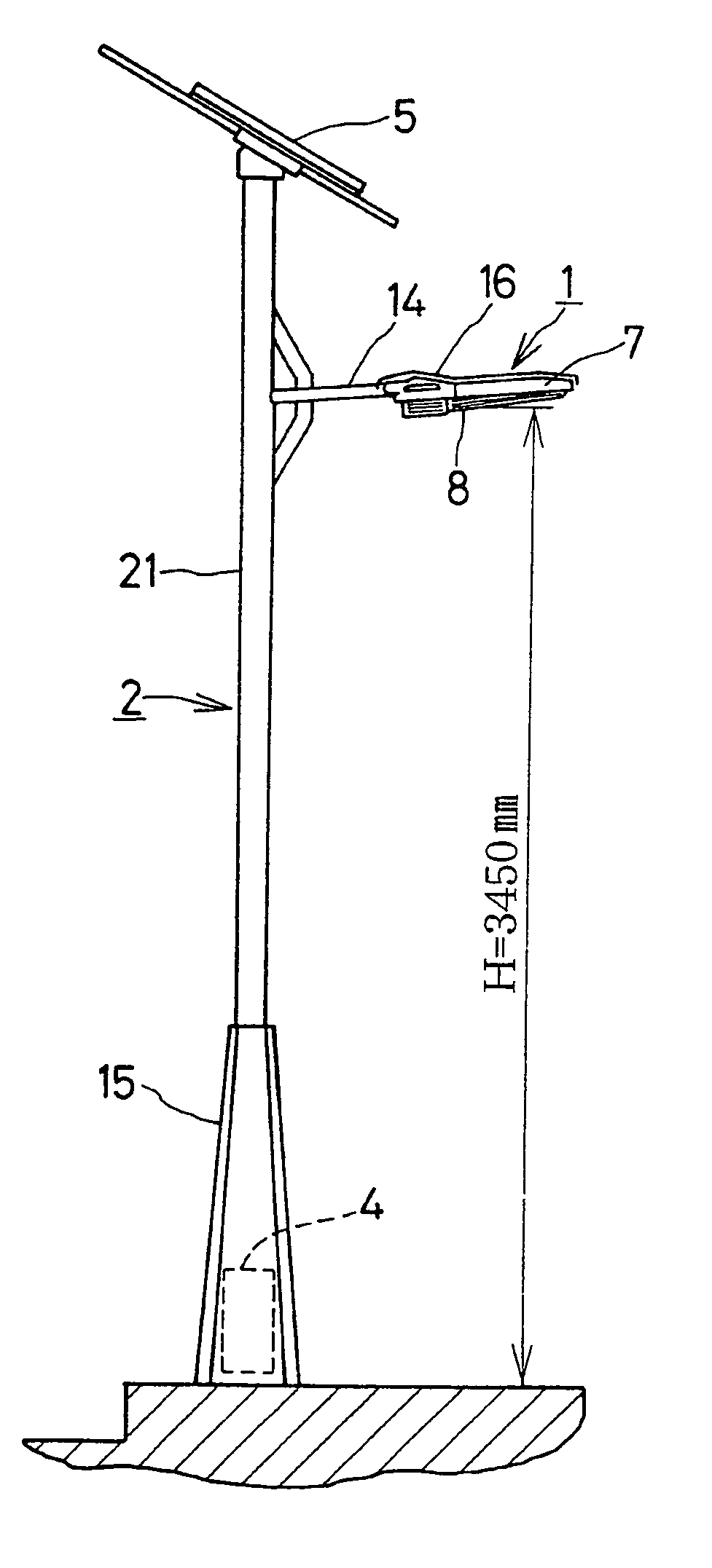
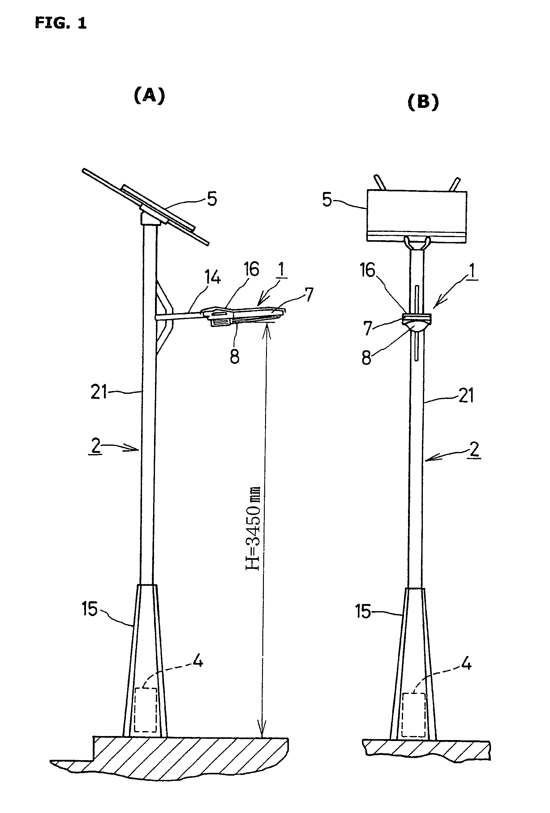
[0025]An embodiment of the invention will now be described with reference to the accompanying drawings. FIG. 1 is an overall view of a white LED lighting device according to this embodiment, with FIG. 1(A) being a front view and FIG. 1(B) a right side view. The white LED lighting device illustrated in FIG. 1 comprises lamp body 1, lamp support 2, power source device 4 and solar cell 5. Lamp support 2 is for example an upright single-column stainless steel support composed of lower bearing portion 15 and pole portion 21, and has protruding support arm 14 situated either on an intermediate portion of the support but nearer the top, as illustrated in FIG. 1, or at the top of the support. Lamp support 2 may be used, for example, as a street light support, in which case it is erected on the pedestrian sidewalk near the roadway shoulder, with support arm 14 projecting out over the sidewalk.

[0026]Power source device 4 is provided with the purpose of supplying electric power to light source...


PUM


Abstract

A white LED lighting device and a light source for white LED lighting that enable an energy-saving, maintenance-free operation while ensuring ample illuminance.
Structure of a light source for white LED lighting, constituted by: inserting and holding a plurality of white LED elements in holding holes in a reflective plate, said plate being constituted by providing a required number of said holding holes, in a matrix-like array of prescribed pitch, in a plate of shape corresponding to the illuminating surface of a lamp body; fixing said plurality of white LED elements at locations 2 to 4 mm behind their respective electrode portions; attaching the positive and negative terminals of the white LED elements to a base plate for the LED elements, said base plate being disposed parallel to and directly behind the reflective plate; and forming, at the positive and negative terminals, a series-parallel electrical network suitable for the applied voltage.

Description

BACKGROUND OF THE INVENTION[0001]1. Field of the Invention[0002]The present invention relates to a white LED lighting device suitable for application to illumination lamps, and specifically to street lamps installed in public places such as streets and parks. The invention also relates to a light source for white LED lighting, for use as the light source in the aforesaid lighting device.[0003]2. Description of Related Art[0004]Illumination in streets and parks has conventionally been provided exclusively by incandescent lamps, mercury lamps and fluorescent lamps. However, because these light sources have a relatively high power consumption, the utilization of light emitting diodes (LEDs), which consume much less electric power than fluorescent lamps, has been studied as a means of saving energy. Nevertheless, due to some of their characteristics, such as strong directivity (being a point light source) and the glaring quality of their light, LEDs are not regarded as suitable for outd...

Claims


Application Information

Patent Timeline
IPC IPC(8): F21S8/08F21V19/00F21V23/00F21S8/04F21S9/02F21S13/10F21V5/02F21V7/05F21V29/00F21W131/103F21Y101/02
CPCF21S8/086F21S9/035F21V5/02F21V19/002F21V19/0025F21V29/83F21V29/15F21V29/004F21W2131/103F21Y2101/02F21Y2105/001Y10S362/80F21Y2105/10F21Y2115/10Y02B20/72F21S13/10
Inventor KISHIMURA, TOSHIJIKISHIMURA, HARUMIMATSUNO, YASUHISAABE, SATOSHITAKAHASHI, TOSHIFUMITSUNASHIMA, TOSHIYUKIOSAWA, MASAKATSUHOTTA, NOBORU
Owner KISHIMURA TOSHIJI
Why Eureka
Try Eureka