Prosthetic foot

a technology for prosthetic feet and feet, applied in the field of prosthetic feet, can solve the problems of unstable anatomical ankle joints, complex joints, and limited development of functional and natural artificial feet, and achieve the effect of simple construction and durabl

Inactive Publication Date: 2005-09-13
COLLEGE PARK IND INC +1
View PDF32 Cites 54 Cited by
  • Summary
  • Abstract
  • Description
  • Claims
  • Application Information

AI Technical Summary

Benefits of technology

[0010]The present invention resides in a prosthetic foot which is simple in construction and durable yet provides a fluid movement without dead or flat spots so as to simulate the natural movement or gait of a foot. The prosthetic foot of the present invention also enables the user to walk stairs, inclined or declined surfaces, or even irregular surfaces.
[0015]Another modification of the prosthetic foot of the present invention can comprise the use of two first springs, each spring extending from the support shank to a pair of laterally spaced toe platforms. Alternatively, the first curvilinear spring can include a forked end, each end being attached to the laterally spaced apart toe platforms. In such an embodiment, the foot bed may include a slit between the laterally spaced apart toe platforms to provide greater freedom of movement between the toe platforms.

Problems solved by technology

The development of a functional and natural artificial foot has been limited only by material and imagination.
However, without all the muscles, tendons and cooperating bone structure of an anatomical foot, the anatomical type ankle joint is too unstable to be practical.
Moreover, another problem with such configurations is the complexity of the several joints.
There are numerous moving parts and joints subject to friction, wear, and failure.
However, no prosthetic foot in the prior art has been completely successful in approximating the performance and response of a natural foot.
Those prior art prosthetic feet which did not utilize a spring-loaded heel experienced a lag or deadness after the user placed the heel on the ground and began to roll the foot forward during the gait cycle.
The response and feel of a natural foot cannot be achieved unless the springs are loaded as the user's weight is placed on the ground rather than after.
Other prior art prosthetic feet utilize a spring-loaded heel which operated on the spring separate from the springs in the toe section effectively stored energy in the heel, but were ineffective in transferring energy from the heel to the toe portion of the prosthetic foot as the foot rolled forward during the gait cycle.
As a result, the user noticed a distinct and unnatural lag or hesitation in rolling the foot forward during the gait cycle, giving the foot an unnatural feel and possibly causing an uneven stride.
One-piece spring devices experienced a lag or deadness after the patient placed the heel on the ground and began to roll forward because the spring design was not suited to absorb and store sufficient energy in the heel and then transfer it to the toe section, thus requiring the toe section to be loaded after the patient's weight had been placed on the ground.
Such dead or flat spots are particularly noticeable when navigating steps or walking backwards.
When experiencing uneven terrain, such as rocks, the prosthetic foot was unable to navigate such obstacles and often caused tension or even hyperflexion of the user's knee or hip.

Method used


Image

  • Prosthetic foot
  • Prosthetic foot
  • Prosthetic foot

Examples


Embodiment Construction

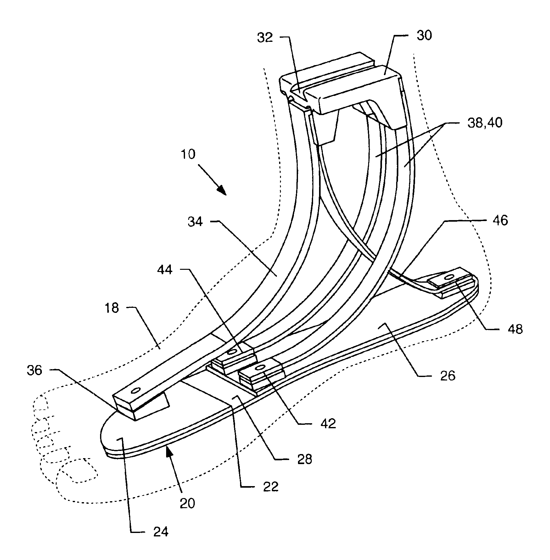
[0029]As shown in the accompanying drawings for purposes of illustration the present invention resides in a prosthetic foot device having design and using materials which result in a more natural and fluid foot movement.

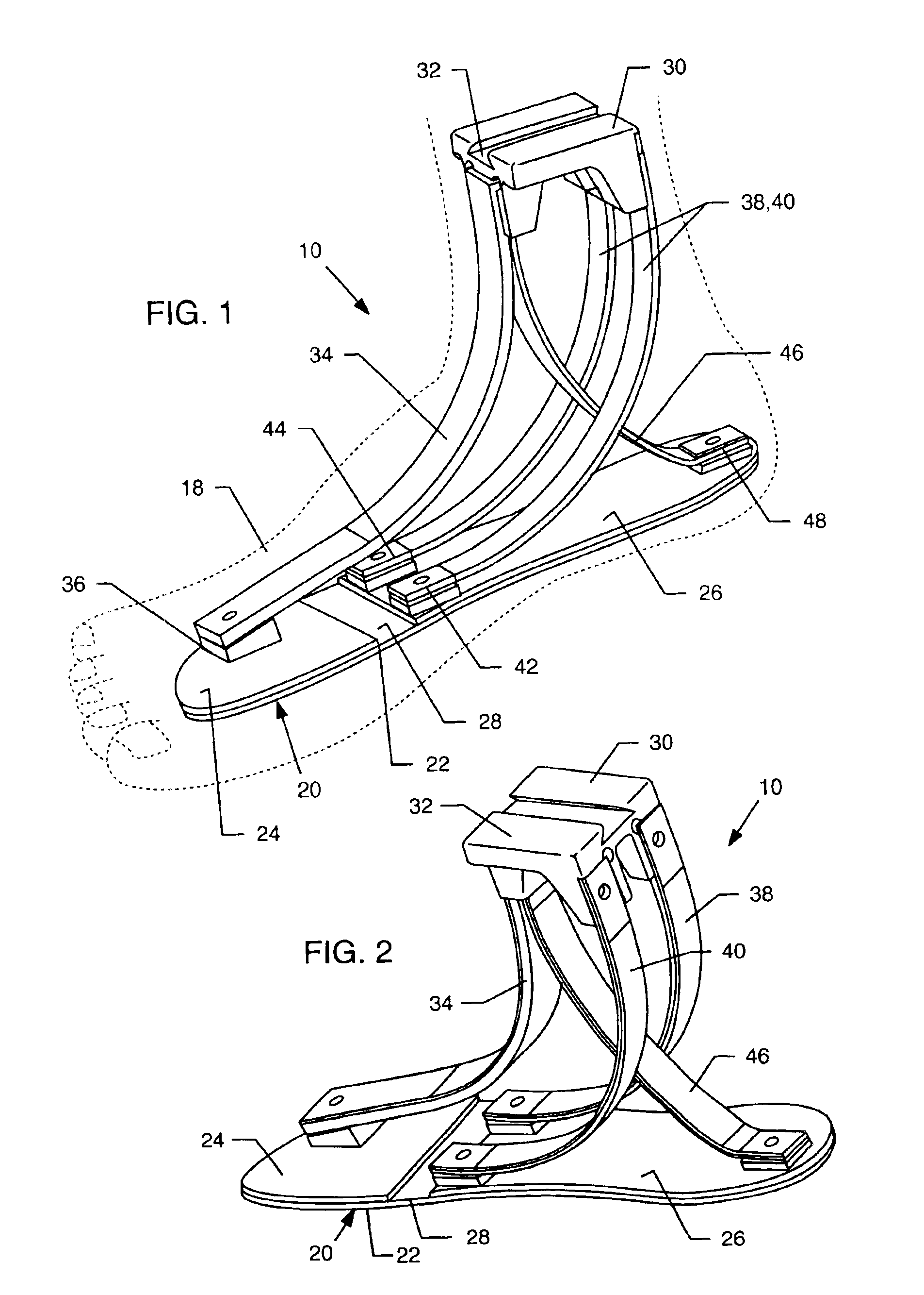
[0030]With reference now to FIGS. 1 and 2, a prosthetic foot 10 embodying the present invention is illustrated. The prosthetic foot device 10 is preferably encased within a rubber encasement 18 which resembles a foot and allows the user to wear shoes and otherwise provide the appearance of a natural foot, as is well-known in the art.

[0031]A ground-engaging base 20 is typically comprised of a generally planar and resiliently flexible foot bed 22. The foot bed 22 can be comprised of many materials, but it has been found that material such as a transmission belt is sufficiently durable and yet provides the characteristics desired by the present invention. However, any flexible material is contemplated by the present invention as comprising the foot bed 22.

[0032]In the e...


PUM


Abstract

A prosthetic foot including a ground-engaging base in the form of a generally planar and resiliently flexible foot bed which extends between two or more platforms to form one or more flexible hinges therebetween. The platforms include a toe platform, a mid-section platform and a heel platform. A support shank is disposed above the platforms so as to be generally positioned above an ankle area of the foot. A first spring extends from the toe platform to the support shank. A second spring extends from the support shank to the mid-section platform. A third spring extends from the support shank to the heel platform. Typically, the springs are curvilinear springs.

Description

BACKGROUND OF THE INVENTION[0001]The present invention generally relates to prosthetic foot devices. More particularly, the present invention relates to a prosthetic foot having a ground-engaging base with at least one flexible hinge and a spring structure to simulate the performance of natural foot movement.[0002]Many individuals have lost a limb for various reasons including war, accident, or disease. In most of these instances, these individuals are aided in their everyday lives by a prosthetic limb. The objective of prosthesis is to provide an artificial limb that simulates the function and natural feel of the replaced limb.[0003]Artificial limbs and particularly prosthetic feet and legs have been known for centuries. The earliest were probably similar to the crude wooden “peg legs”. These early devices enabled the user to stand and to walk awkwardly, usually with the additional aid of a crutch or cane. Over time, designers of artificial or prosthetic feet attempted to duplicate...

Claims


Application Information

Patent Timeline
Patent Type & Authority Patents(United States)
IPC IPC(8): A61F2/66A61F2/60A61F2/00A61F2/50
CPCA61F2/66A61F2002/30387A61F2002/30433A61F2002/5001A61F2002/5003A61F2002/5039A61F2002/6621A61F2002/6635A61F2002/6642A61F2002/665A61F2002/6664A61F2220/0025A61F2220/0041A61F2240/001A61F2310/00023
Inventor SULPRIZIO, MICHAEL SCOTT
Owner COLLEGE PARK IND INC
Why Eureka
Try Eureka