Brushless permanent magnet wheel motor with variable axial rotor/stator alignment

a permanent magnet wheel and motor technology, applied in the direction of optical signals, magnetic circuit shapes/forms/construction, cycle equipment, etc., can solve the problems of increasing reducing the driving range of the vehicle, and fully electric vehicles inherently have limited driving ranges

Inactive Publication Date: 2005-09-13
DURA TRAC MOTORS INC
View PDF76 Cites 64 Cited by
  • Summary
  • Abstract
  • Description
  • Claims
  • Application Information

AI Technical Summary

Problems solved by technology

While the use of electric vehicles will completely eliminate the use of fossil fuels, there are a number of disadvantages associated with designs that incorporate electric motors into the drive systems of motor vehicles, including both fully electric vehicles and hybrid vehicles which utilize a combination of fossil fueled engines and electric motors.
The power transmission devices and accessorial devices entail not only additional weight, but also effect the efficiency of power transmission which increases a vehicle's energy consumption and decreases the driving range of the vehicle.
It is widely known that fully electric vehicles inherently have limited driving ranges because of limitations on storage batteries, and that concerns about short driving ranges constitutes one of the major factors that prevents such vehicles from being readily accepted by the general public.
Control is however generally limited by the characteristics of the electric motors and generally involves merely varying the electrical energy supplied to the individual motors.
The back-emf base speed characteristic that protects permanent magnet motors also tends to limit the dynamic rpm range.
While such configurations provide the necessary high torque to overcome inertia, it results in a low base speed and a limited top speed.
The costs of such contactors and their contact wear tend to negate the advantages of a high durability brushless motor.
This latter approach typically requires contactors and increases heating effects in the stator.
This method increases system costs and decreases reliability and efficiency.
These factors add to the complicated design and effect durability, and cost.
The design of Rao requires extensive machining of the radial magnet tracks which increases costs and adds to the complexity.
In addition, maintaining a sufficient level of balance of this magnet rotor is complicated by several factors.
Small variations in the resultant in the individual magnet positions would have a disastrous effect on the balance at high rotor speeds.
These factors would necessarily adversely affect the ability to reduce back-emf of the motor and operate above the base speed.

Method used


Image

  • Brushless permanent magnet wheel motor with variable axial rotor/stator alignment
  • Brushless permanent magnet wheel motor with variable axial rotor/stator alignment
  • Brushless permanent magnet wheel motor with variable axial rotor/stator alignment

Examples


Embodiment Construction

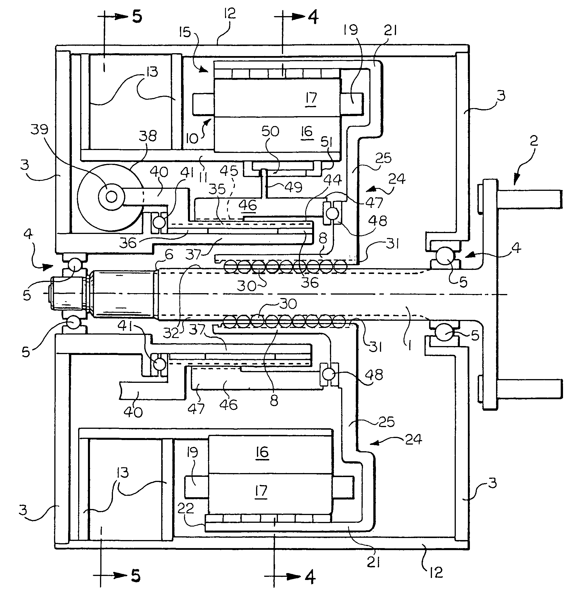
[0037]The present invention is directed to brushless permanent magnet wheel motor designs that are configured to be used as hub motors in motor vehicles and to brushless permanent magnet alternator designs that can be used in wind turbine generators systems and motors for water craft. Even more particularly, the present invention relates to brushless permanent magnet motor and alternator designs that allow for variable axial rotor / stator or rotator / armature alignment.

[0038]The present invention provides separate brushless permanent magnet motors for one or more wheels of a wheeled vehicle. Each wheel motor according to the present invention includes a motor shaft which are is coupled to separate wheel hub, wheel rim or other structure that supports a tire thereon for rotation therewith.

[0039]The motor shaft is supported within a stator by housing structure for rotational movement within the stator and is coupled to the stator so as to prevent relative axial movement between the moto...


PUM


Abstract

A brushless permanent magnet electric machine with a fixed radial air gap is operated to a much higher speed than normal maximum speed by the reduction in effective magnet pole strength. Permanent magnets are supported on the inner surface of an axially movable cylindrical shell. A plurality of magnetic poles provided with wire coils are supported on a stationary cylindrical member cooperate with the permanent magnets on the axially movable cylindrical shell to either cause, or react to, rotation of the axially movable cylindrical shell. The axially movable cylindrical shell and cylindrical member are coaxial. The cylindrical shell is axially movable with respect to the cylindrical member.

Description

TECHNICAL FIELD[0001]The present invention relates primarily to electric drive systems for motor vehicles. More particularly, the present invention relates to brushless permanent magnet wheel motor designs that are configured to be used as hub motors in motor vehicles and to brushless permanent magnet alternator designs that can be used in wind turbine generators systems and motors for marine craft. Even more particularly, the present invention relates to brushless permanent magnet motor and alternator designs that allow for variable axial rotor / stator or rotator / armature alignment.BACKGROUND ART[0002]In response to environmental concerns it has been the goal of the automobile industry to develop motor vehicles that use less fossil fuel. While the use of electric vehicles will completely eliminate the use of fossil fuels, there are a number of disadvantages associated with designs that incorporate electric motors into the drive systems of motor vehicles, including both fully electri...

Claims


Application Information

Patent Timeline
Patent Type & Authority Patents(United States)
IPC IPC(8): H02K7/12H02K7/10H02K21/12H02K21/00H02K11/00H02K21/22H02K16/00H02K29/06
CPCH02K7/12H02K21/222H02K29/06H02K11/0015H02K16/00Y02E10/725B60L2220/14B60L2220/16B60L2220/44B60L2220/50H02K11/21Y02E10/72Y02T10/64
Inventor ZEPP, LAWRENCE P.MEDLIN, JERRY W.
Owner DURA TRAC MOTORS INC
Why Eureka
Try Eureka