Identification and tracking of moving objects in detected synthetic aperture imagery

a technology of synthetic aperture and detection image, applied in the field of synthetic aperture imagery, can solve the problems of limiting the resolution of angle coordinate, moving objects may not be visible in traditional sar imagery, drawbacks encountered, etc., and achieve the effect of reducing the amount of processing and reducing the corresponding processing tim

Inactive Publication Date: 2005-09-13
LOCKHEED MARTIN CORP
View PDF71 Cites 62 Cited by
  • Summary
  • Abstract
  • Description
  • Claims
  • Application Information

AI Technical Summary

Benefits of technology

[0011]An additional object of the present invention is to provide a mover-detection process that is separate and distinct from a SAR image formation process, wherein the mover-detection process may be performed at a later time and at a different location.
[0012]It is a further object of the present invention to provide a process for detecting and tracking movers in a SAR image that is relatively unaffected by the velocities or trajectories of the movers, wherein high speed and / or maneuvering movers do not require special consideration.
[0018]The detecting of the signature may further include determining linear filtering parameters for separating a signal from noise in the SAR image. However, the reading of the signature may also include non-linear filtering of the SAR image to recover very low-intensity signals. For example, if the separating of the signal from noise is unsuccessful, then the reading of the signature may include implementing pre-whitening filtering and non-linear filtering of the synthetic aperture image for separating the signal from the noise. Separation of desired low-intensity signals may include a use of stochastic methods, such as adding noise to a given signal in order to increase a sensitivity of signal detection. The reading of the signature may include identifying movers at several instants equally spaced in time in order to identify a direction and velocity of the movers.
[0026]By identifying movers at spaced instants in time over an entire collection interval, the position / velocity profile of the movers over the interval may be identified. Therefore, for example, an image processor can easily be reconfigured to generate a high-resolution image of a mover. Thereby, an amount of processing and a corresponding processing time may be reduced, and special collections and tasks are not required. In addition, the mover-detection process may be separate and distinct from the image formation process, and may be performed at a later time and at a different location.

Problems solved by technology

The range resolution can be less than a meter but conventional microwave antenna beamwidths may limit the resolution in the angle coordinate (i.e. cross range limitation).
However, ISARs use the motion of a viewed object to synthesize a large aperture antenna and not the motion of the radar platform itself.
While conventional systems have been quite successful in presenting images to trained personnel for interpretation, drawbacks have been encountered.
Specifically, moving objects may not be visible in traditional SAR imagery due to the fact that radar energy may be widely scattered in the image by the processor.
Since such mover detection methods are a part of the image formation process and cannot be readily separated therefrom, special tasking, special collections, or special image processing are conventionally required for detecting moving objects using SAR imaging.

Method used


Image

  • Identification and tracking of moving objects in detected synthetic aperture imagery
  • Identification and tracking of moving objects in detected synthetic aperture imagery
  • Identification and tracking of moving objects in detected synthetic aperture imagery

Examples


Embodiment Construction

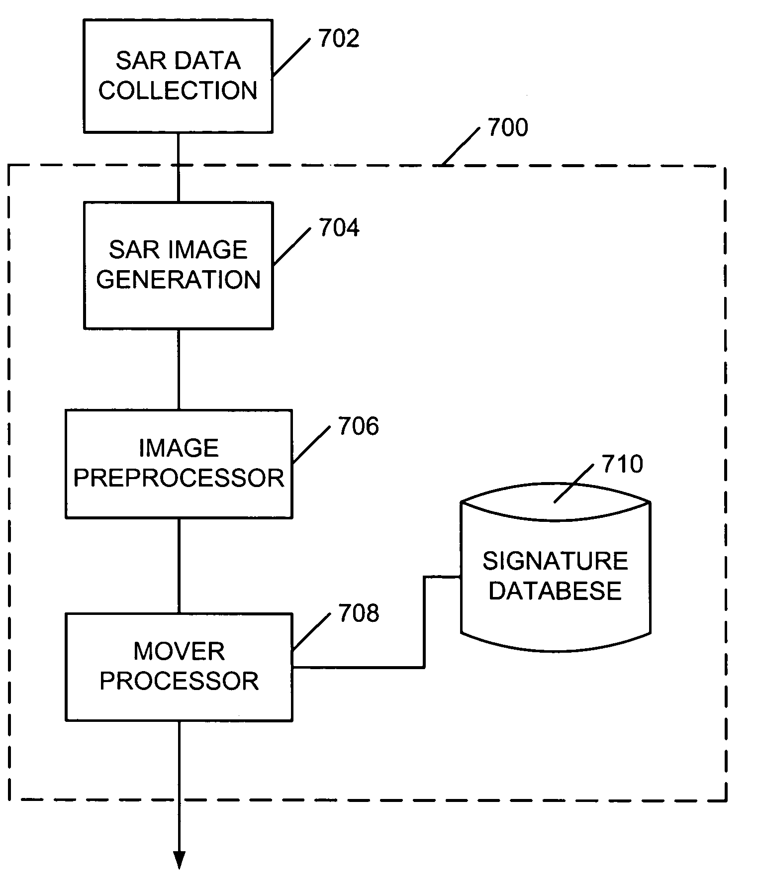
[0039]FIGS. 1–9 illustrate various features of the method and system of the present invention. Generally, the method and system of the present invention are directed to processing image data relating to images collected by a synthetic aperture radar imaging system that may use real and / or complex image data to detect and / or classify a cultural object and / or a replicated object. The method and system of the present invention are particularly useful for detecting and / or tracking moving objects. For example, a method and system of the present invention may be used to detect and / or track moving objects that are not readily visible in an image or that are moving at a high rate of speed. The present method uses SAR image formation for describing the signature of a moving object in order to identify what the given inputs actually represent.

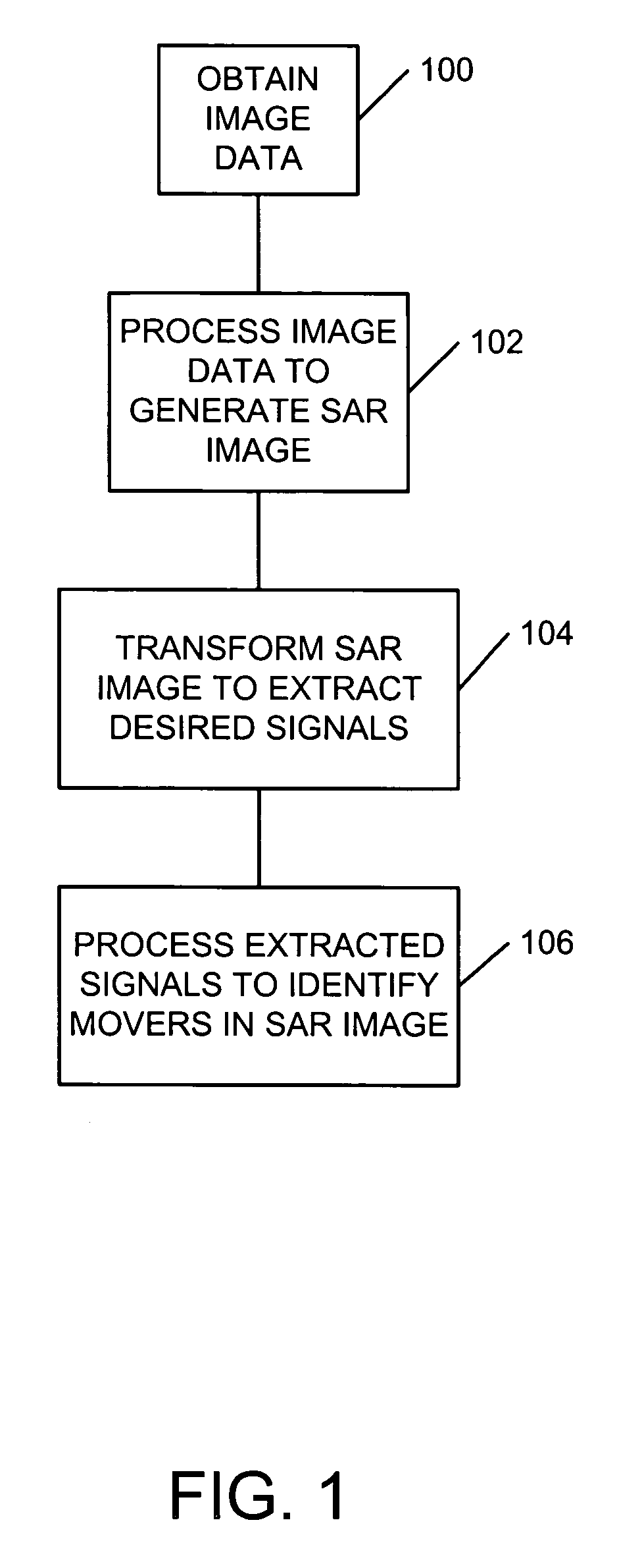
[0040]Referring to FIG. 1, disclosed therein is a method for processing synthetic aperture radar (SAR) data so as to perform one or more functions which...


PUM


Abstract

A method of tracking a moving object in an image created by use of a synthetic aperture includes identifying a plurality of receive phase centers for an image collector, obtaining a synthetic aperture image using the plurality of receive phase centers, and reading a signature of the moving object based on the synthetic aperture image, where the reading of the signature includes identifying, in the synthetic aperture image, as a function of image collection time, a presence of the moving object. The reading of the signature may also include identifying a changing position of the moving object, and may include associating a plurality of range difference values with respective ones of the plurality of phase centers. A signature of a scatterer may be formed using only its associated ΔR-versus-time profile. The presence of a mover in the image may be determined by filtering the image to detect all or part of a signature, or by using one or more signatures to train a neural network to observe the mover directly.

Description

[0001]This application claims priority from U.S. Provisional Patent Application Ser. No. 60 / 422,326, filed on Oct. 30, 2002, which is hereby incorporated by reference in its entirety.FIELD OF THE INVENTION[0002]The present invention relates to synthetic aperture imagery, and more particularly, to the identification and tracking of moving objects by using multiple receive phase centers for a synthetic aperture radar (SAR) image collector.BACKGROUND OF THE INVENTION[0003]An imaging radar transmits electromagnetic waves to objects within a region of interest that scatter, or reflect, the energy according to the properties of such objects (e.g. physical attributes). When the radar receives reflected waves from the objects a spatial distribution of the reflected energy may be constructed by a processor. This distribution defines a radar image that may be displayed as a 3 dimensional representation of the scene or any 2-dimensional representation thereof.[0004]A real-aperture imaging rada...

Claims


Application Information

Patent Timeline
Patent Type & Authority Patents(United States)
IPC IPC(8): G01S13/00G01S13/90
CPCG01S13/9029G01S13/9027
Inventor BRACE, FRED C.PETTY, JOE V.
Owner LOCKHEED MARTIN CORP
Why Eureka
Try Eureka