Servo writing a disk drive by synchronizing a servo write clock to a high frequency signal in a spiral track

a technology of servo write clock and spiral track, which is applied in the field of disk drives, can solve the problems of synchronizing the timing error of the servo write clock with the external servo writer, the cost of external servo writers and the need for a clean room environment,

Inactive Publication Date: 2005-09-13
WESTERN DIGITAL TECH INC
View PDF18 Cites 199 Cited by
  • Summary
  • Abstract
  • Description
  • Claims
  • Application Information

AI Technical Summary

Benefits of technology

[0012]In one embodiment, the control circuitry within the disk drive is used to read the spiral tracks in order to synchronize the servo write clock. In an alternative embodiment, an external product servo writer is used to read the spiral tracks in order to synchronize the servo write clock.
[0013]The present invention may also be regarded as a disk drive comprising a disk having a plurality of spiral tracks, wherein each spiral track comprises a high frequency signal interrupted at a predetermined interval by a sync mark. The disk drive further comprises an actuator arm, a head connected to a distal end of the actuator arm, and a voice coil motor for rotating the actuator arm about a pivot to position the head radially over the disk. The head internal

Problems solved by technology

However, external servo writers are expensive and require a clean room environment so that a head positioning pin can be inserted into the head disk assembly (HDA) without contaminating the disk.
Thus, external servo writers have become an expensive

Method used


Image

  • Servo writing a disk drive by synchronizing a servo write clock to a high frequency signal in a spiral track
  • Servo writing a disk drive by synchronizing a servo write clock to a high frequency signal in a spiral track
  • Servo writing a disk drive by synchronizing a servo write clock to a high frequency signal in a spiral track

Examples


Embodiment Construction

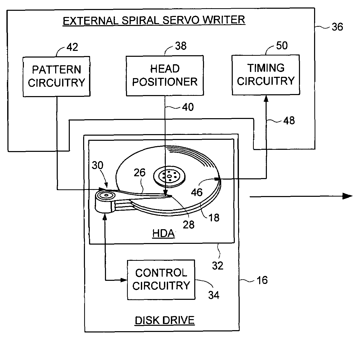
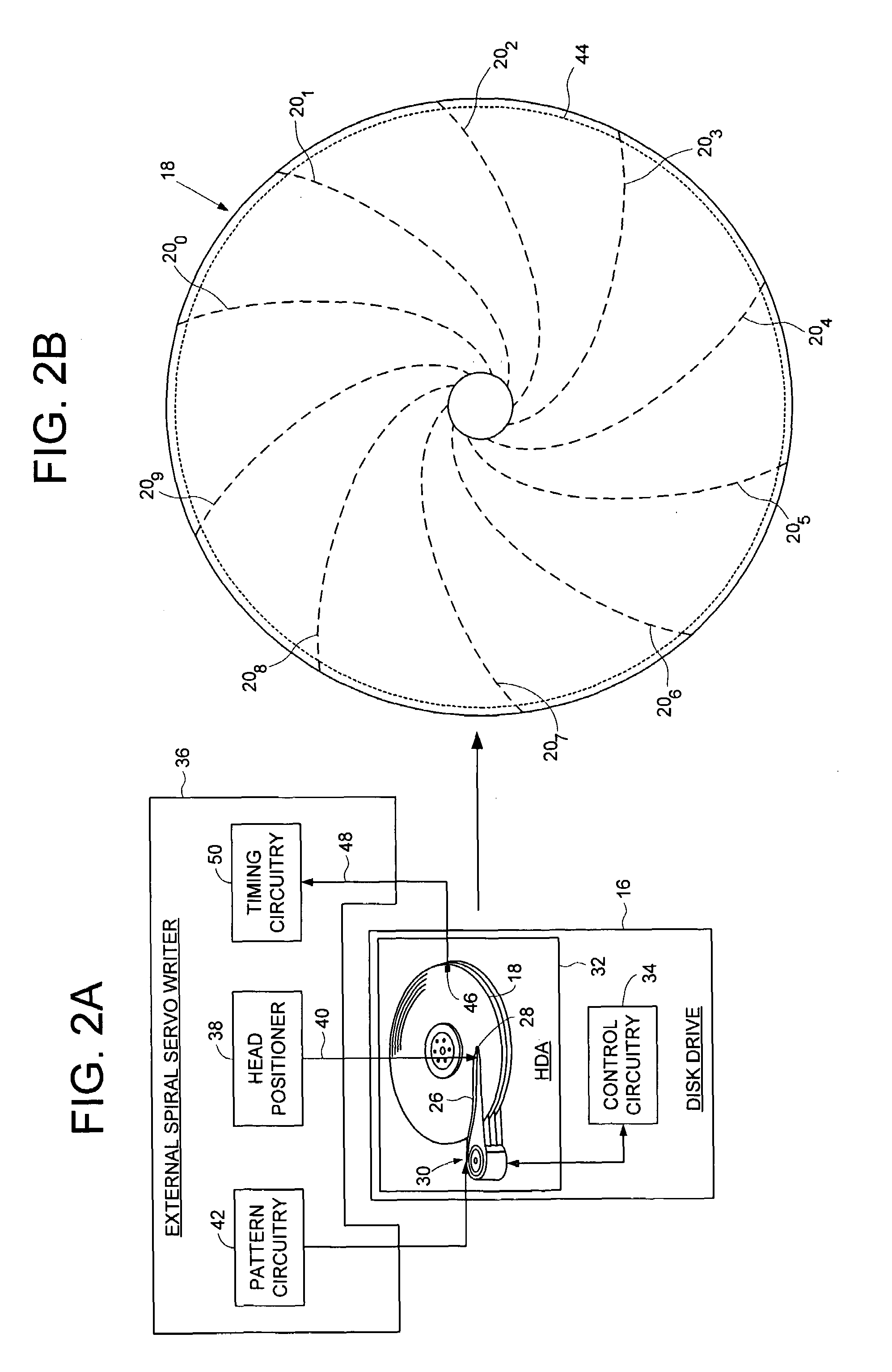
[0026]FIGS. 2A and 2B show a disk drive 16 according to an embodiment of the present invention comprising a disk 18 having a plurality of spiral tracks 200–20N, wherein each spiral track 20 comprises a high frequency signal 22 interrupted at a predetermined interval by a sync mark 24 (FIG. 3B). The disk drive 16 further comprises an actuator arm 26, a head 28 connected to a distal end of the actuator arm 26, and a voice coil motor 30 for rotating the actuator arm 26 about a pivot to position the head 28 radially over the disk 18. The head 28 internal to the disk drive 16 is used to read the high frequency signal 22 in the spiral tracks 20 to generate a position error signal used to maintain the head 28 along a substantially circular target path. The sync marks 24 in the spiral tracks 20 are read to generate a spiral sync mark detect signal, and a coarse timing recovery measurement is generated in response to the spiral sync mark detect signal. A fine timing recovery measurement is g...


PUM


Abstract

A method of writing product servo sectors to a disk of a disk drive is disclosed. A plurality of spiral tracks are written to the disk, wherein each spiral track comprises a high frequency signal interrupted at a predetermined interval by a sync mark. During the product servo writing process, the sync marks in the spiral tracks are read to generate a coarse timing recovery measurement, and the high frequency signal in the spiral tracks is read to generate a fine timing recovery measurement. The coarse and fine timing recovery measurements are processed to synchronize a servo write clock used to write the product servo sectors to the disk. In one embodiment the control circuitry within the disk drive synchronizes the servo write clock by reading the spiral tracks, and in an alternative embodiment an external product servo writer synchronizes the servo write clock by reading the spiral tracks.

Description

BACKGROUND OF THE INVENTION[0001]1. Field of the Invention[0002]The present invention relates to disk drives for computer systems. More particularly, the present invention relates to servo writing a disk drive by synchronizing a servo write clock to a high frequency signal in a spiral track.[0003]2. Description of the Prior Art[0004]When manufacturing a disk drive, product servo sectors 20–27 are written to a disk 4 which define a plurality of radially-spaced, concentric data tracks 6 as shown in the prior art disk format of FIG. 1. Each product servo sector (e.g., servo sector 24) comprises a preamble 8 for synchronizing gain control and timing recovery, a sync mark 10 for synchronizing to a data field 12 comprising coarse head positioning information such as a track number, and servo bursts 14 which provide fine head positioning information. During normal operation the servo bursts 14 are processed by the disk drive in order to maintain a head over a centerline of a target track w...

Claims


Application Information

Patent Timeline
IPC IPC(8): G11B21/02G11B5/596
CPCG11B5/59655G11B5/59661G11B5/59633
Inventor LEE, TEHRI S.
Owner WESTERN DIGITAL TECH INC
Why Eureka
Try Eureka