Suspension design for the co-located PZT micro-actuator

a micro-actuator and co-located technology, applied in the direction of maintaining head carrier alignment, recording information storage, instruments, etc., can solve the problems of insufficient support space for connecting the micro-actuator, increasing the stiffness of the suspension assembly, and difficult micro-actuator bonding using gold ball bonding or solder bump bonding methods

Inactive Publication Date: 2005-09-13
SAE MAGNETICS (HK) LTD
View PDF5 Cites 45 Cited by
  • Summary
  • Abstract
  • Description
  • Claims
  • Application Information

AI Technical Summary

Problems solved by technology

This design results in an increased stiffness in the suspension assembly due to the electric trace connection.
Further, micro-actuator bonding, using methods such as gold ball bonding or solder bump bonding, is difficult

Method used


Image

  • Suspension design for the co-located PZT micro-actuator
  • Suspension design for the co-located PZT micro-actuator
  • Suspension design for the co-located PZT micro-actuator

Examples


Embodiment Construction

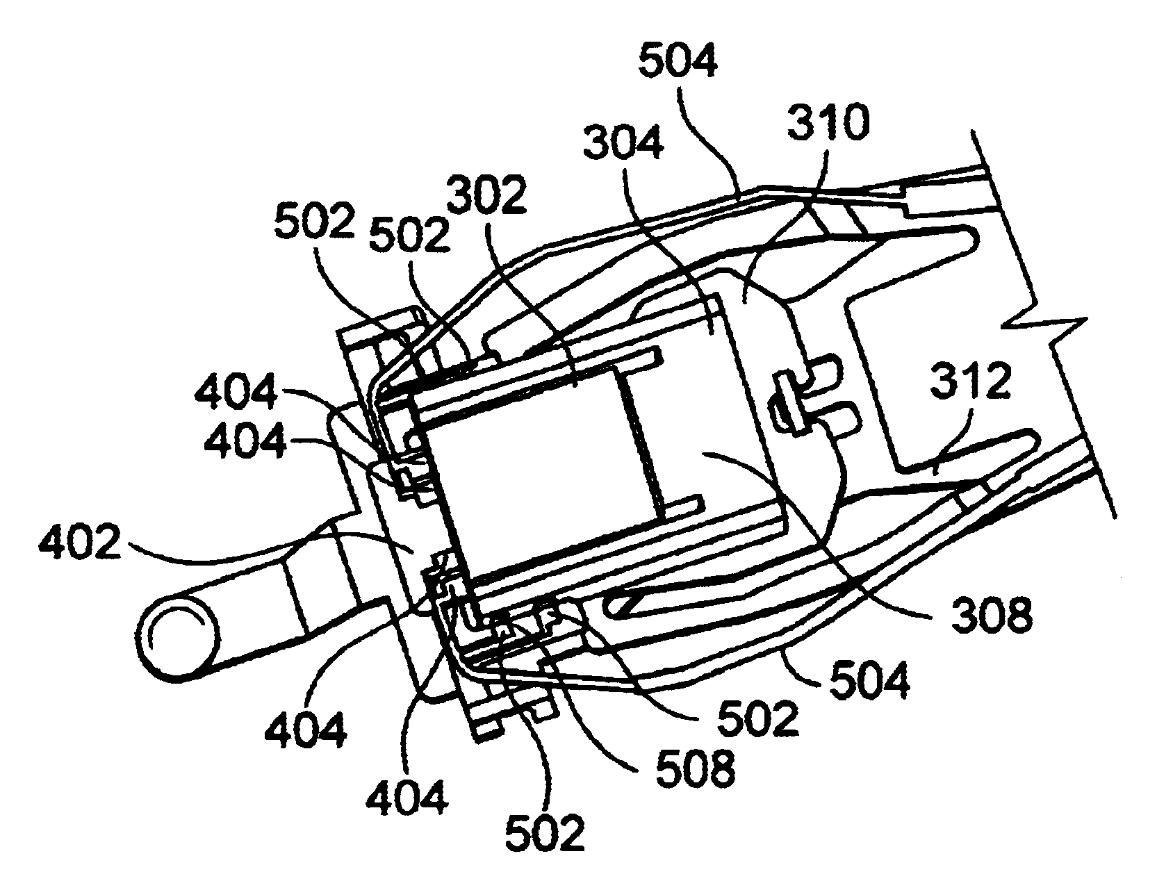
[0011]A suspension design for a micro-actuator that reduces suspension tongue stiffness and a method of manufacturing the HGA with the micro-actuator are disclosed. In one embodiment, the micro-actuator has a base piece with two arms extending from the base piece. The electric contact pads for the arms are situated on the exterior of the arms at the end opposite the base piece. In one embodiment, the electric contact pads are electrically coupled to the same connection plate as the magnetic read / write head. This design provides enough support space for the electric coupling of the micro-actuator as well as the magnetic read / write head, preventing the damage caused during the bonding process. The electric connection traces for the micro-actuator are consolidated with the traces for the magnetic read / write head on the outriggers of the suspension tongue, reducing the stiffness of the tongue itself.

[0012]Illustrated in an upside-down orientation, FIG. 3a describes one embodiment of a h...


PUM


Abstract

A micro-actuator that reduces suspension tongue stiffness and a method of manufacturing the micro-actuator are disclosed. In one embodiment, the micro-actuator has a base piece with two arms extending from the base piece. The electric contact pads for the arms are situated on the exterior of the arms at the end opposite the base piece. In one embodiment, the electric contact pads are electrically coupled to the same connection plate that the magnetic read/write head is coupled to, reducing the number of connection traces.

Description

BACKGROUND INFORMATION[0001]The present invention relates to magnetic hard disk drives. More specifically, the present invention relates to electrical connections for micro-actuators.[0002]In the art today, different methods are utilized to improve recording density of hard disk drives. FIG. 1 provides an illustration of a typical disk drive with a typical drive arm 102 configured to read from and write to a magnetic hard disk 104. Typically, voice-coil motors (VCM) 106 are used for controlling a hard drive's arm 102 motion across a magnetic hard disk 106. Because of the inherent tolerance (dynamic play) that exists in the placement of a recording head 108 by a VCM 106 alone, micro-actuators 110 are now being utilized to ‘fine-tune’ head 108 placement. A VCM 106 is utilized for course adjustment and the micro-actuator 110 then corrects the placement on a much smaller scale to compensate for the VCM's 106 (with the arm 102) tolerance. This enables a smaller recordable track width, in...

Claims


Application Information

Patent Timeline
IPC IPC(8): G11B5/55G11B5/48G11B5/56
CPCG11B5/4826G11B5/4853G11B5/5552G11B5/56Y10T29/49027Y10T29/42Y10T29/49025Y10T29/49032
Inventor YAO, MING GAOSHIRAISHI, MASASHIXIE, YI RU
Owner SAE MAGNETICS (HK) LTD
Why Eureka
Try Eureka