System for identifying clusters in scatter plots using smoothed polygons with optimal boundaries

a technology of optimal boundaries and scatter plots, applied in the field of optimal boundaries for cluster identification in scatter plots, can solve the problems of difficult to distinguish between cells which fall into regions of apparent overlap, contribute inaccuracy to population counts and percentages being reported, and their detection and classification are both difficult and important, so as to facilitate batch processing and facilitate the processing of other related data sets.

Inactive Publication Date: 2005-09-13
BECTON DICKINSON & CO
View PDF30 Cites 121 Cited by
  • Summary
  • Abstract
  • Description
  • Claims
  • Application Information

AI Technical Summary

Benefits of technology

[0020]In accordance with another embodiment of the present invention, the cluster finder algorithm implementing the method described herein is implemented via a programmable processing device. A display provides a visual indication of the plurality of clusters. The processing device is operable to provide a user with the boundary of one of the plurality clusters on the display when selected via a user input device. The processing device can also alter a boundary of a cluster in response to a user commands generated via the user input device. The processing device facilitates batch processing by generating a template after a first data set is gated. The template facilitates processing other related data sets to locate corresponding clusters.

Problems solved by technology

As a result, often it is difficult to distinguish between cells which fall into regions of apparent overlap between clusters.
In such cases, cells can be inadvertently classified in a wrong cluster, and thus, contribute inaccuracy to the population counts and percentages being reported.
These residual cells are present in very low frequencies (i.e., their presence is rare and thus their occurrence in a large sample is a “rare event”), and thus, their detection and classification are both difficult and important.
However, there are some limitations to this method.
For example, because of the fixed size, shape and orientation of the boundary surface, some cells can be inadvertently classified in a wrong cluster or omitted from inclusion within the boundary, and therefore contribute inaccuracy to the population counts and percentages being reported.

Method used


Image

  • System for identifying clusters in scatter plots using smoothed polygons with optimal boundaries
  • System for identifying clusters in scatter plots using smoothed polygons with optimal boundaries
  • System for identifying clusters in scatter plots using smoothed polygons with optimal boundaries

Examples


Embodiment Construction

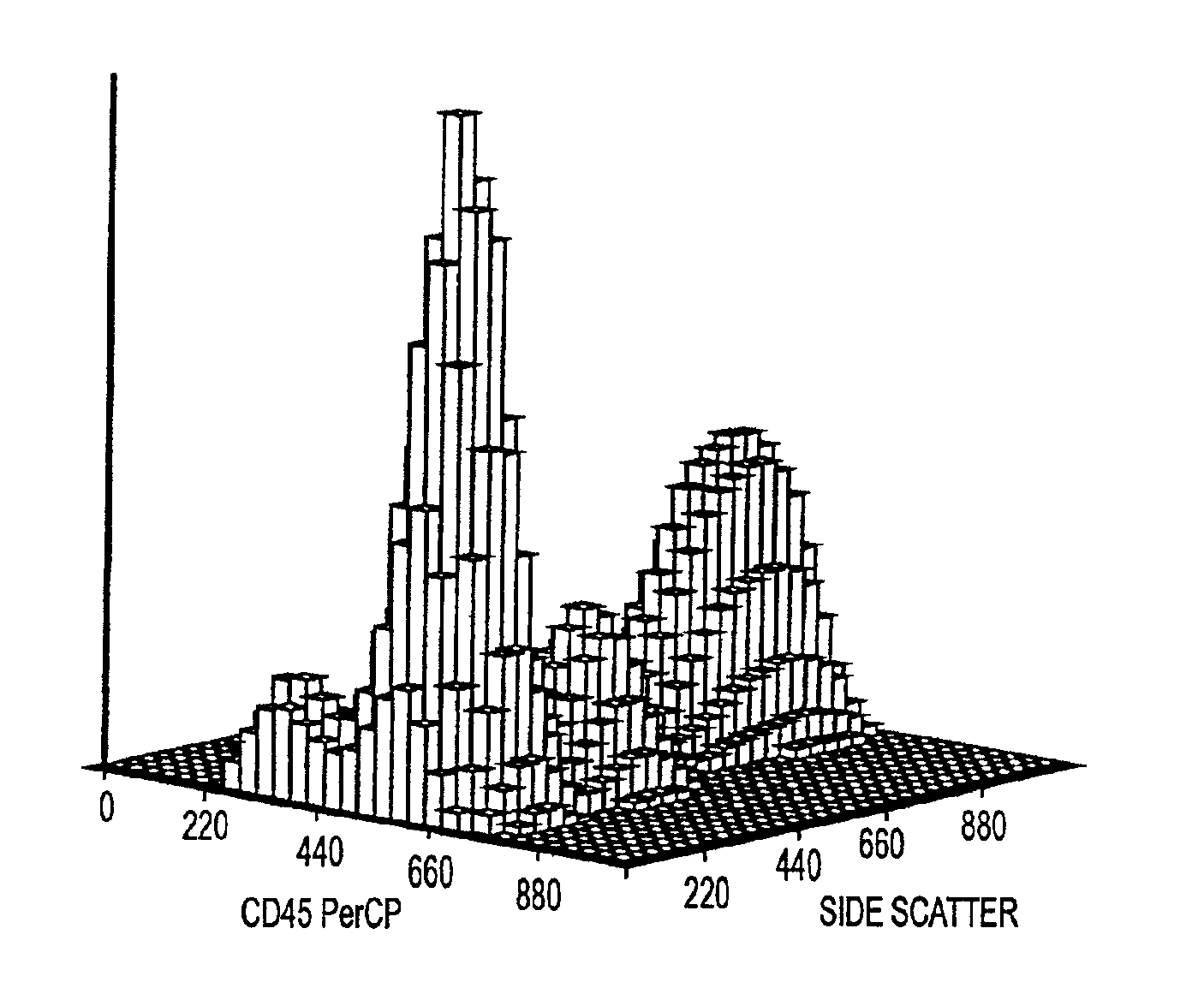
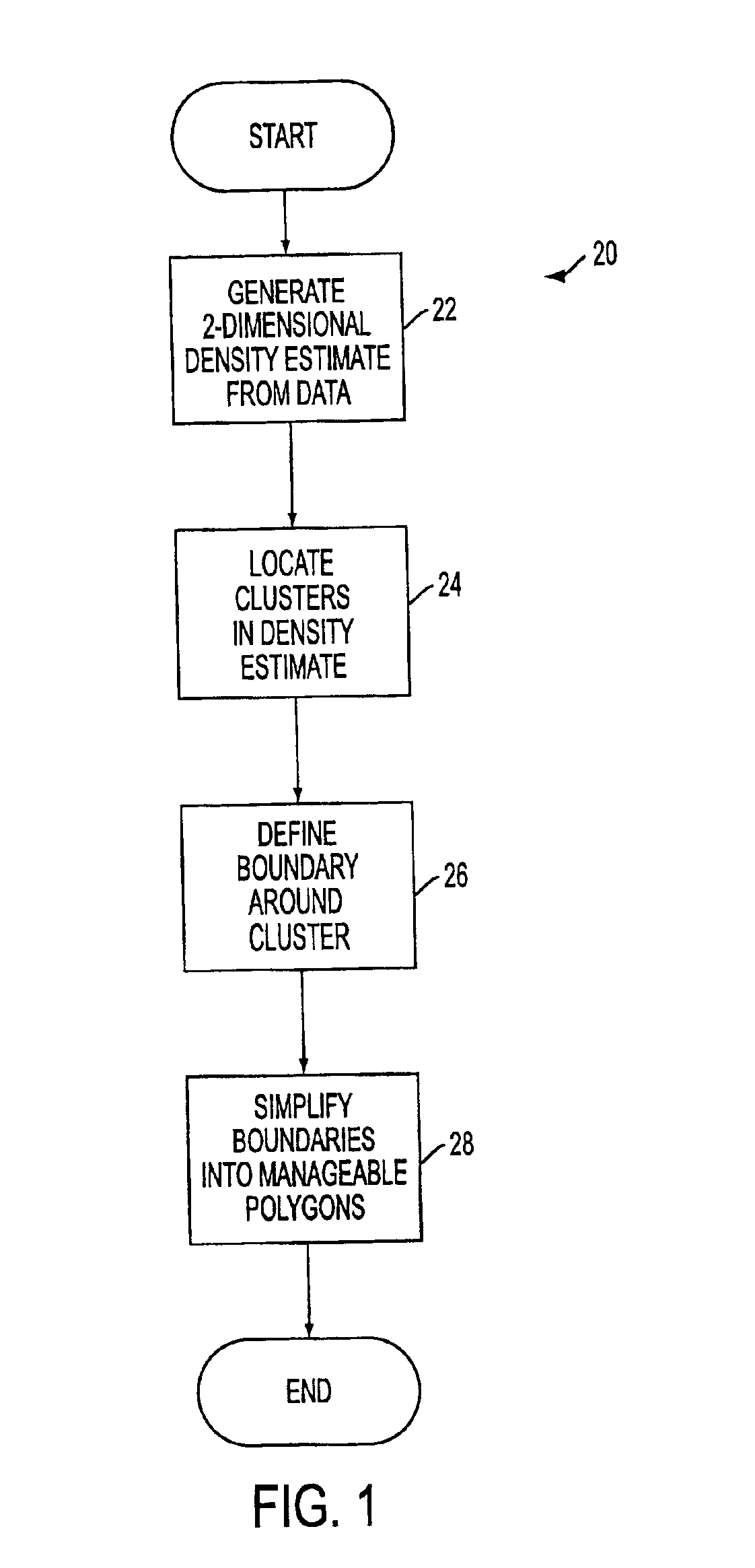
[0033]In accordance with an embodiment of the present invention, a cluster finder algorithm 20 is provided which can be used with event data such as scatter plots of data obtained via flow cytometry. The cluster finder algorithm 20 is illustrated in FIG. 1 and will be described in further detail below. It is to be understood that the cluster finder algorithm 20 can be used with essentially any application employing a two-dimensional data set.

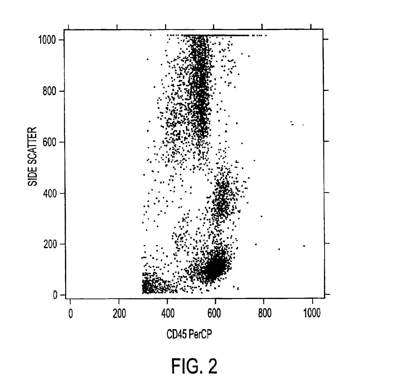
[0034]The cluster finder algorithm 20 is preferably implemented in software code that is executed by a programmable digital computer (FIG. 12). The processing device implementing the cluster finder algorithm 20 can receive the data to be processed via an electronic file comprising a table having two columns of numbers corresponding to points (x,y) in the scatter plot, for example. An exemplary scatter plot is shown in FIG. 2. The exemplary data provided in FIG. 2 will be processed in accordance with the present invention and described below in c...


PUM

PropertyMeasurementUnit
wavelength of emissionaaaaaaaaaa
densityaaaaaaaaaa
areaaaaaaaaaaa

Abstract

An apparatus and method for identifying clusters in two-dimensional data by generating a two-dimensional histogram characterized by a grid of bins, determining a density estimate based on the bins, and identifying at least one cluster in the data. A smoothed density estimate is generated using a Gaussian kernel estimator algorithm. Clusters are identified by locating peaks and valleys in the density estimate (e.g., by comparing slope of adjacent bins). Boundaries (e.g., polygons) around clusters are identified using bins after bins are identified as being associated with a cluster. Boundaries can be simplified (e.g., by reducing the number of vertices in a polygon) to facilitate data manipulation.

Description

[0001]The present invention claims benefit under 35 U.S.C. § 119(e) of a U.S. Provisional Patent Application of Dwayne Yount et al. entitled “Hardware and Electronics Architecture for a Flow Cyometer”, Ser. No. 60 / 203,515, filed May 11, 2000, of a U.S. Provisional Patent Application of Michael Lock et al. entitled “Cluster Finder Algorithm for Flow Cytometer”, Ser. No. 60 / 203,590, filed May 11, 2000, of a U.S. Provisional Patent Application of Michael Goldberg et al. entitled “User Interface and Network Architecture for Flow Cytometer”, Ser. No. 60 / 203,585, filed May 11, 2000 and of a U.S. Provisional Patent Application of John Cardott et al. entitled “Digital Flow Cytometer”, Ser. No. 60 / 203,577, filed May 11, 2000, the entire contents of each of said provisional patent applications being incorporated herein by reference.CROSS-REFERENCE TO RELATED APPLICATIONS[0002]Related subject matter is disclosed in a copending U.S. Patent Application of Pierce O. Norton entitled “Apparatus and...

Claims


Application Information

Patent Timeline
Patent Type & Authority Patents(United States)
IPC IPC(8): G01N15/14G06K9/62G01N33/48G01N15/10G01N21/49G06F17/18
CPCG01N15/1456G06K9/00147G06K9/6226G01N2015/1006G01N2015/1413G01N2015/1477G06V20/698G06F18/2321
Inventor LOCK, MICHAEL D.DALAL, SUNIL S.GLUHOVSKY, ILYA
Owner BECTON DICKINSON & CO
Why Eureka
Try Eureka