
Valve with unilaterally constrained piezoelectric bending element as actuating device

a piezoelectric bending element and valve technology, applied in the field of valves, can solve the problems of negative impact and high operating energy input, and achieve the effects of low triggering power, good switching-over dynamics, and high force density

Inactive Publication Date: 2005-09-20
HOERBIGER AUTOMOTIVE KOMFORTSYST
View PDF7 Cites 5 Cited by
  • Summary
  • Abstract
  • Description
  • Claims
  • Application Information

AI Technical Summary

Benefits of technology

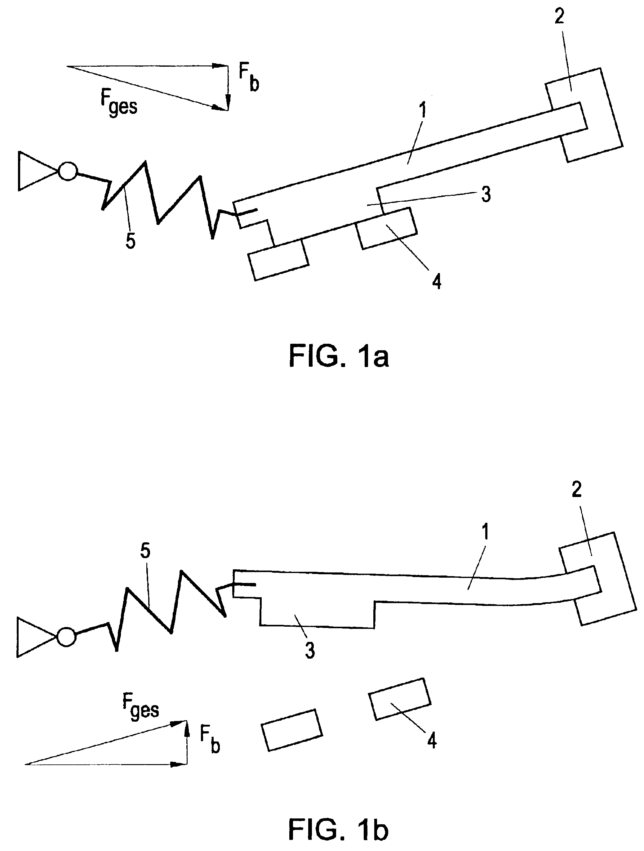
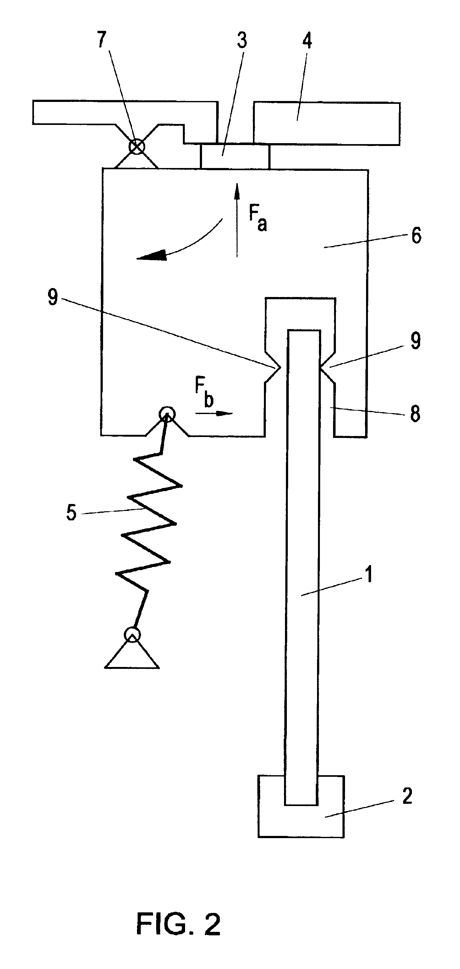
[0007]To achieve this objective according to the invention the actuating device is realized as a unilaterally constrained piezoelectric bending element. With their very high density of force accompanied by minimal triggering power and good switch-over dynamics, these bending elements, which are in fact known in the art, have all prerequisites for a large stroke in the presence of the most minimal dimensions. In conjunction with the support of the change-over on the part of the elastic element, which exercises its largest force in the neutral position of the bending element and the applied force of which drops parallel to the increasing displacement and thereby the decreasing displacement force of the bending element, it is possible to utilize the full no-load stroke of the bending element and it is possible to increase the achievable stroke considerably—which is accompanied in the valves, in turn, by an increase of the flow-through output.
[0019]The applicability and variability of the valve can be further enhanced if a pressure sensor is integrated in the valve.

Problems solved by technology

In most instances, however, this has a negative impact on the switch-over dynamics of the valve at least in one direction, and the valve requires a high operating energy input in order to overcome this preload.

Method used


Image

  • Valve with unilaterally constrained piezoelectric bending element as actuating device
  • Valve with unilaterally constrained piezoelectric bending element as actuating device
  • Valve with unilaterally constrained piezoelectric bending element as actuating device

Examples


Embodiment Construction

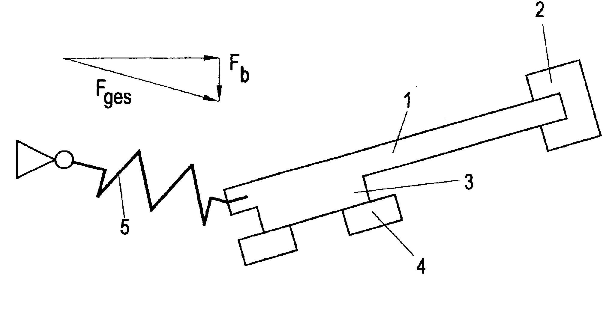
[0027]A piezoelectric bending element 1 is constrained with its one end at a location 2 inside the housing of the valve or in a structure connected therewith. In the resting position that is shown in FIG. 1a, in which no voltage is applied, the bending element 1 pushes a sealing device 3 against a valve seat 4. The closing force consists of the mechanical properties of the bending element 1 and, additionally, the action of the pressure spring 5, with the latter essentially being arranged as aligned with the bending element 1 and / or with the latter enclosing no more than an obtuse angle near 180° with the bending element; thus, the larger force component of the pressure spring acts principally in the longitudinal direction of the bending element 1 and, therefore, in a perpendicular direction relative to the direction of displacement of the bending element. The force in the resting position is determined by the part Fb of the spring force Fges[=Ftotal] in the direction of displacement...


PUM


Abstract

Valve with a displaceable actuating device that controls the movements of at least one actual sealing element for opening and closing, and the actuating device is loaded with an elastic element essentially in a perpendicular direction relative to the direction of displacement, and the longitudinal axis of the actuating device and the force exercised by the elastic element are aligned in one position of the actuating device between its two extreme positions. In order to realize a valve that can be electrically switched using minimal currents and that is characterized, in particular, by its small construction size but that is still able to achieve large regulating distances, the actuating device is a unilaterally constrained piezoelectric bending element.

Description

BACKGROUND OF THE INVENTION[0001]1. Field of the Invention[0002]The invention relates to a valve with a displaceable actuating device which controls the movements of at least one actual sealing device for opening and / or closing, and the actuating device is loaded with an elastic element, essentially perpendicularly in relation to the direction of displacement and the longitudinal axis of the actuating device as well as the force that is exercised by the elastic element are aligned in one position of the actuating device between its two extreme positions; and / or the invention relates to a valve with a displaceable actuating device that controls the movements of at least one actual sealing device for opening and / or closing, and an elastic element acts essentially perpendicularly in relation to the direction of displacement of the actuating device, and the longitudinal axis of the actuating device as well as the force that is exercised by the elastic element are essentially aligned.[00...

Claims


Application Information

Patent Timeline
Patent Type & Authority Patents(United States)
IPC IPC(8): F16K31/00F16K31/02
CPCF16K31/006Y10T137/87217Y10T137/87772Y10T137/86847
Inventor DORFLER, ERICHRUSS, BERNHARDSTRASSER, GUNTHERTELTSCHER, RAINER
Owner HOERBIGER AUTOMOTIVE KOMFORTSYST
Learn More