Power unit mounting for motor vehicles with collision separation

a technology for power units and motor vehicles, applied in the direction of bogie-underframe connections, mechanical devices, vibration dampers, etc., can solve problems such as consumption work, and achieve the effects of reducing the amount of material used

Inactive Publication Date: 2005-09-20
MAGNA STEYR FAHRZEUGTECHN
View PDF4 Cites 1 Cited by
  • Summary
  • Abstract
  • Description
  • Claims
  • Application Information

AI Technical Summary

Benefits of technology

[0015]In a refinement, the ramp of the supporting plate has a stiffening bead as far as the first bent-over section and lateral incisions in the first bent-over section and the following, second bent-over section extends again over the entire width of the supporting plate. As a result, the transition from the supporting plate to the separating device can easily be bent, with the result that the separating device is rapidly fitted to the connection and the part forming the separating device itself is very stiff, thus enabling it to act simultaneously on a plurality of fastening points lying next to one another. This stiffness can be further increased by the second bent-over section having reinforcing ribs in the longitudinal direction. These ribs also contribute to the better introduction of force from the assembly to the separating device. The two bent-over sections may also be two adjoining zones of a bent-over section with relatively large radii of curvature.

Problems solved by technology

However, the supporting plate may also be designed in such a manner that it becomes deformed after the first fastening point is separated, and thereby consumes work.

Method used


Image

  • Power unit mounting for motor vehicles with collision separation
  • Power unit mounting for motor vehicles with collision separation
  • Power unit mounting for motor vehicles with collision separation

Examples


Embodiment Construction

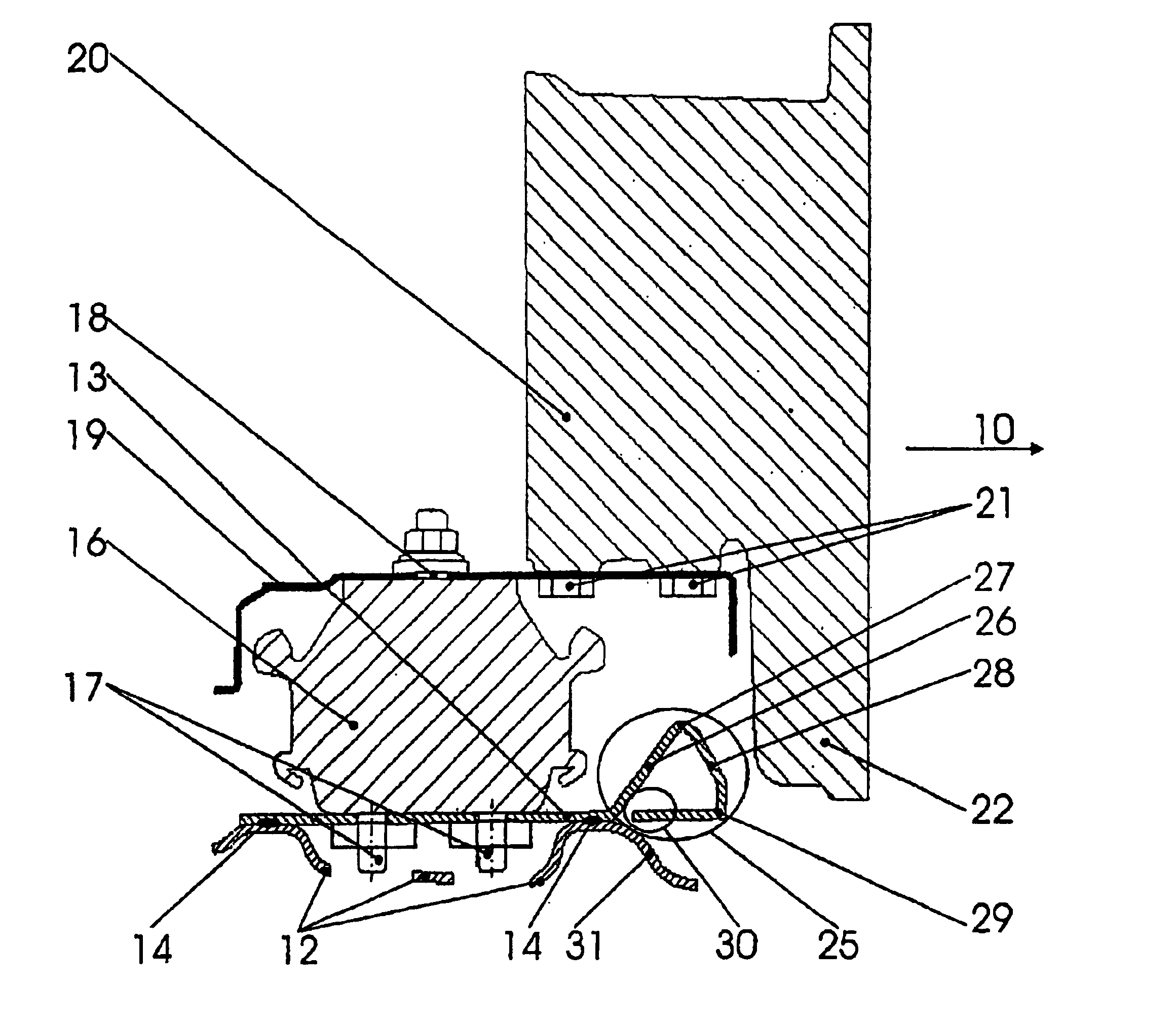
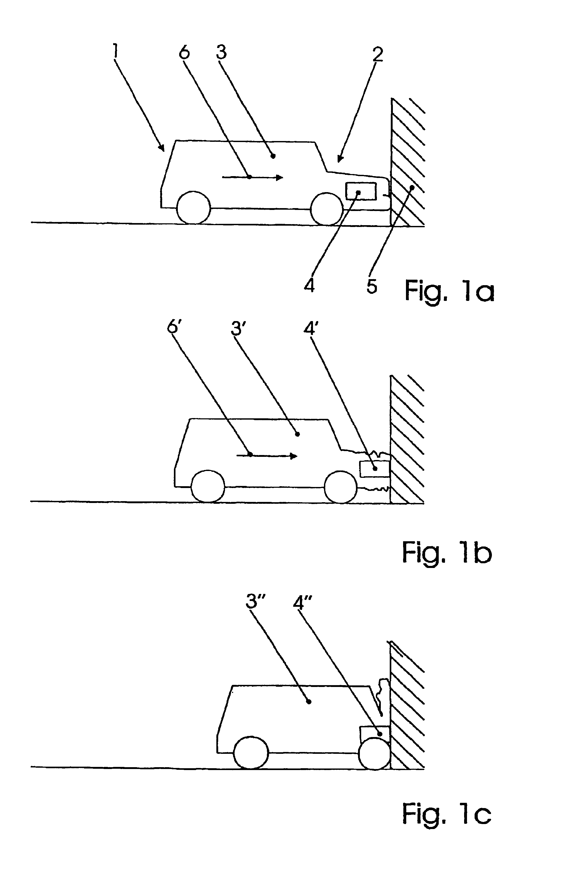
[0025]In FIG. 1, a motor vehicle is referred to in general by 1, its front end by 2 and its cell, which is the space in which the passengers are situated, by 3. An assembly is indicated in the front end 2 and is referred to by 4. In this case, it is the engine / transmission block. In FIG. 1a, the vehicle which is traveling at a certain speed (arrow 6), is illustrated at the moment in which it comes into contact at its frontmost point with a collision object, a fixed obstacle or another vehicle. This is the beginning of the collision. The front end 2 is first of all deformed until the assembly 4 has also reached the obstacle 5, as illustrated in FIG. 1b. Up to this point, the front end has been deformed with energy being consumed, the cell 3 of the vehicle having been decelerated. At the moment illustrated in FIG. 1b, if there were a fixed connection between the engine 4 and the vehicle 1, the deformation of the front end would come to a stop, since the assembly 4 itself is scarcely d...


PUM


Abstract

A mounting for a power unit for motor vehicles, comprises a support and a support plate fixed thereto, which may be detached in the case of a collision, whereby the support plate is connected to the support in a number of places. A power unit mounting may be achieved which guarantees a steady deceleration, whereby a separating device is provided, which separates the support plate from the support. The separating device can be a part of the support plate or fixed thereto and is forced between support plate and support in the case of a collision.

Description

BACKGROUND OF THE INVENTION[0001]The invention relates to a support for an assembly for motor vehicles, comprising a crossbeam which is fastened to the body of the assembly, and a supporting plate which is fastened on said crossbeam in a manner enabling it to be detached in the event of a collision, on which the assembly is supported, the supporting plate being connected to the crossbeam at a number of points, and at least part of the assembly being situated upstream of the support in the direction of travel, and comprising a separating device which separates the supporting plate from the crossbeam in the event of a collision.[0002]An assembly is understood to be the drive train or part of it, in particular the engine / transmission block and, if appropriate, an adjoining differential or power take-off gear. These assemblies are virtually all accommodated nowadays in the front end of the vehicle. The crossbeam is a crossrail which connects the longitudinal crossbeams of the vehicle bo...

Claims


Application Information

Patent Timeline
Patent Type & Authority Patents(United States)
IPC IPC(8): B60K5/12
CPCB60K5/1275
Inventor HUBER, DENNIS
Owner MAGNA STEYR FAHRZEUGTECHN
Why Eureka
Try Eureka