Subaperture chemical mechanical planarization with polishing pad conditioning

Inactive Publication Date: 2005-09-20
REVASUM INC
View PDF11 Cites 6 Cited by
  • Summary
  • Abstract
  • Description
  • Claims
  • Application Information

AI Technical Summary

Benefits of technology

[0011]The present invention achieves these benefits in the context of known process technology and known techniques in the art. The present invention provides an improved planarization apparatus for chemical mechanical planarization (CMP). Specifically, the present invention provides an improved planarization apparatus that provid

Problems solved by technology

During IC manufacturing, the various masking and processing steps typically result in the formation of topographical irregularities on the wafer surface.
This problem is exacerbated by the use of multilevel interconnects.
A wafer surface that is not sufficiently planar, will result in structures that are poorly defined, with the circuits either being nonfunctional or, at best, exhibiting less than optimum performance.
Many other limitations, however, exist with CMP.
The large polishing pad is often difficult to control and requires expensive and difficult to control slurries.
Additionally, the large polishing pad is often difficult to remove and replace.
The large pad is also expensive and consumes a large foot print in the fabrication facility.
These and other limitations still exist with CMP and the like.

Method used


Image

  • Subaperture chemical mechanical planarization with polishing pad conditioning
  • Subaperture chemical mechanical planarization with polishing pad conditioning
  • Subaperture chemical mechanical planarization with polishing pad conditioning

Examples


Embodiment Construction

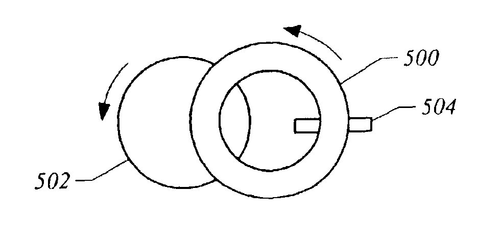
[0029]According to specific embodiments of the present invention, a technique including a device for chemical mechanical planarization of objects is provided. In an exemplary embodiment, the invention provides a polishing pad, which is mounted on a cap. The cap is rotatably coupled to a drive head of a polishing apparatus. The apparatus includes a smaller polishing pad, relative to the size of the object being polished.

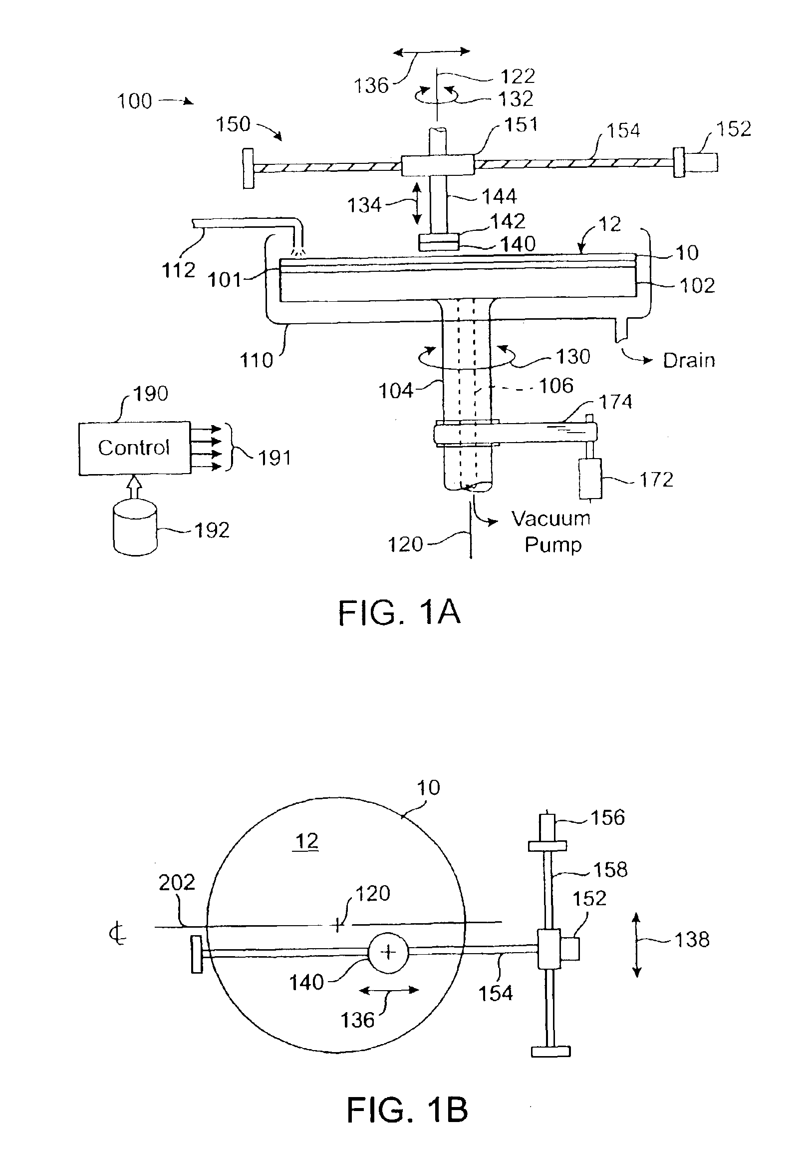
[0030]Referring to FIG. 1A, a chemical-mechanical planarization apparatus 100 includes a chuck 102 for holding a wafer 10 in position during a polishing operation. The apparatus shown is merely an example and has been simplified to facilitate a discussion of the salient aspects of the invention. As such, the figure should not unduly limit the scope of the claims herein. One of ordinary skill in the art would recognize many other variations, alternatives, and modifications.

[0031]The chuck includes a drive spindle 104 which is coupled to a motor 172 via a drive belt 174...


PUM

PropertyMeasurementUnit
Diameteraaaaaaaaaa
Areaaaaaaaaaaa

Abstract

Embodiments of the present invention are directed to polishing an object with polishing pad conditioning. In one embodiment, a method for polishing an object comprises placing a contact portion of a polishing pad in contact with a target surface of the object to be planarized over a contact area which is smaller in area than the target surface; conditioning a noncontact portion of the polishing pad which is not in contact with the target surface of the object; and moving the polishing pad relative to the target surface of the object to move the noncontact portion in contact with the target surface of the object and move the contact portion out of contact with the target surface of the object.

Description

[0001]The present application is a divisional of U.S. patent application Ser. No. 09 / 709,972, filed Nov. 10, 2000 now U.S. Pat. No. 6,547,651, which is based on and claims the benefit of U.S. Provisional Patent Application No. 60 / 164,640, filed Nov. 10, 1999, and which is a continuation-in-part of U.S. patent application Ser. No. 09 / 693,040, entitled “Quick Pad Release Device for Chemical Mechanical Planarization,” filed Oct. 20, 2000 now U.S. Pat. No. 6,464,574, the entire disclosures of which are incorporated herein by reference.BACKGROUND OF THE INVENTION[0002]The present invention relates to the manufacture of objects. More particularly, the invention provides a technique including a device for planarizing a film of material of an article such as a semiconductor wafer. However, it will be recognized that the invention has a wider range of applicability; it can also be applied to flat panel displays, hard disks, raw wafers, MR heads, precision optics and lens, and other objects t...

Claims


Application Information

Patent Timeline
IPC IPC(8): B24B37/04B24B37/20B24B37/24B24B37/26
CPCB24B37/20B24B37/245B24B37/26B24D9/085
Inventor BOYD, JOHN M.LACY, MICHAEL S.HALLEY, DAVID G.
Owner REVASUM INC
Why Eureka
Try Eureka