
Conditioning tools and techniques for chemical mechanical planarization

a technology of mechanical planarization and conditioning tools, applied in the field of abrasives technology, can solve problems such as cost increases, and achieve the effect of reducing the lift-up of brazing films

Inactive Publication Date: 2008-11-06
SAINT GOBAIN ABRASIFS INC +1
View PDF100 Cites 75 Cited by
  • Summary
  • Abstract
  • Description
  • Claims
  • Application Information

AI Technical Summary

Benefits of technology

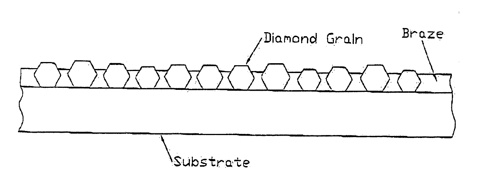
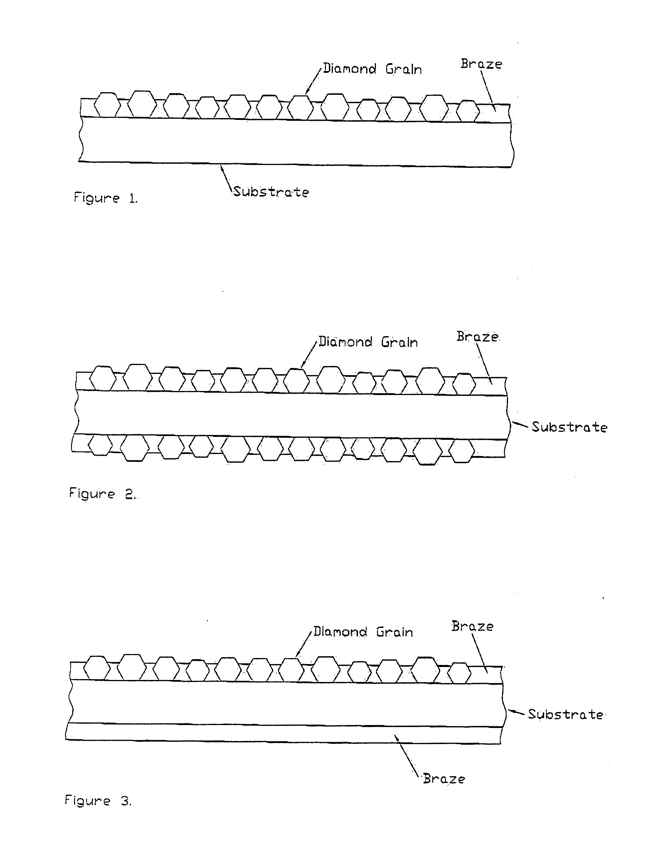
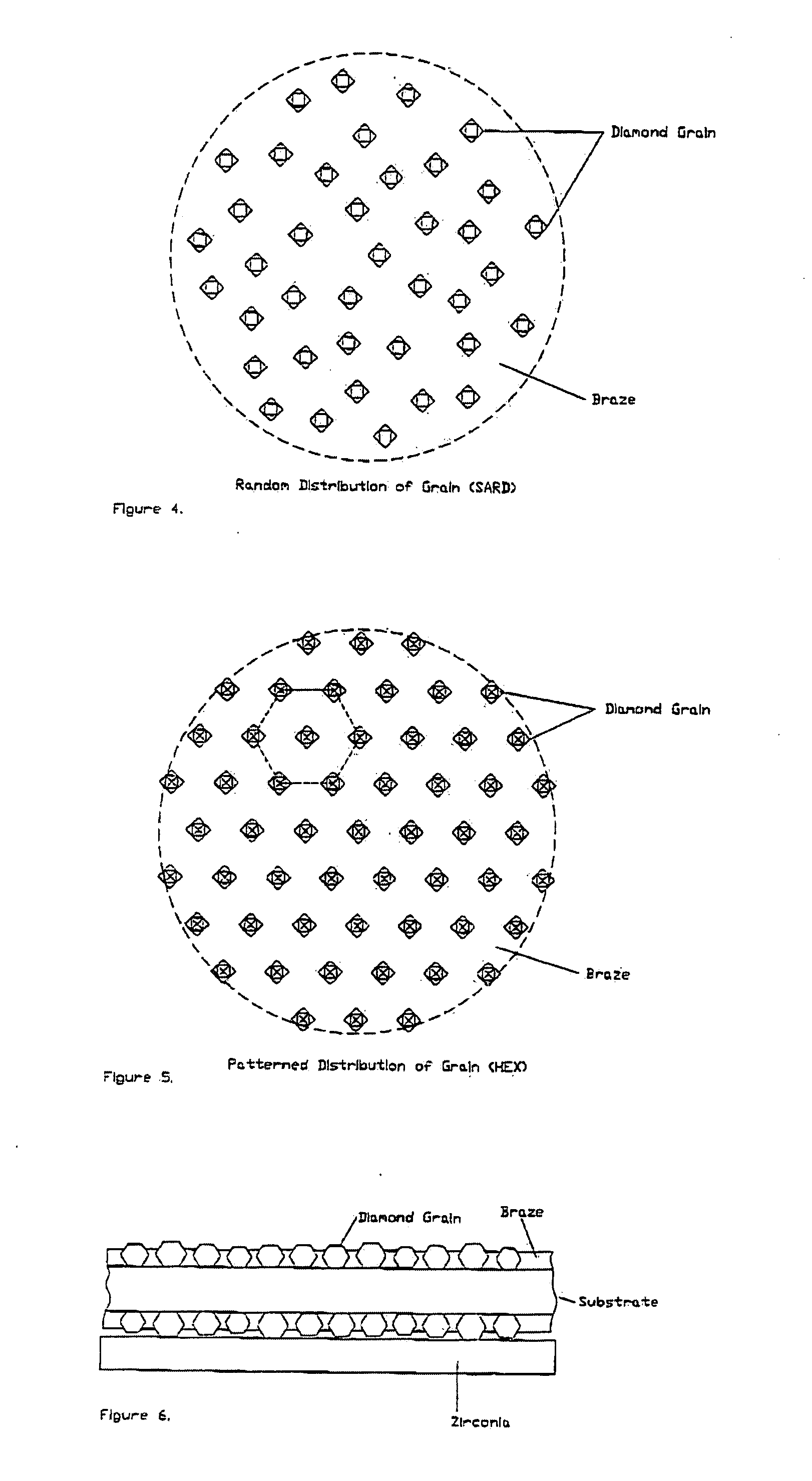
[0006]One embodiment of the present invention is a tool for conditioning chemical mechanical planarization (CMP) pads. The tool includes a support member with at least two sides (e.g., front and back sides) and a plurality of abrasive particles, wherein the abrasive particles are coupled to at least one of the sides of the support member by a metal bond, and at least about 95% (by weight) of the abrasive particles have a particle size of less than about 85 micrometers. The tool has an abrasive particle concentration of greater than about 4000 abrasive particles/inch2 (620 abrasive particles/centimeter2) and an inter-particle spacing so that substantially no abrasive particles are touching other abrasive particles (e.g., less than 5% by volume of abrasive particles are touching other abrasive particles). In some such cases, the abrasive particle concentration is greater than about 10000 abrasive particles/inch2 (1550 abrasive particles/centimeter2). The tool may have an out-of-flatness, for example, of less than about 0.01 inches, and in some cases, less than about 0.002 inches. In one particular case, the support member is a stainless steel disk, and the abrasive particles are diamonds. In one such case, the metal bond is a brazing alloy, and the diamonds are brazed to the first side of the support member by the brazing alloy. In another such case, the diamonds are brazed to both the first side and the second side of the support member by the brazing alloy. In another such case, the diamonds are brazed only to the first side of the support member by the brazing alloy, and the second side of the support member has braze

Problems solved by technology

Otherwise, process instability and deteriorated wafer surfaces generally result in cost increases.

Method used


Image

  • Conditioning tools and techniques for chemical mechanical planarization
  • Conditioning tools and techniques for chemical mechanical planarization
  • Conditioning tools and techniques for chemical mechanical planarization

Examples


example 1

[0040]FEPA D76 200 / 230 mesh diamonds (source: Element Six Ltd) were subsieved to −85 micrometers +65 micrometers. 3.6183 gram of diamonds were sieved using the sieves (U.S. Sieve Series) shown below. The following distribution of diamonds on or through sieves of the given mesh was obtained:

SieveGrams%On 11600On 850.10422.88On 751.269735.09On 652.135959.03Through 650.10853.00Through 49003.6183100.00

[0041]Accordingly, 35.09% by total weight of sieved diamonds went through the sieve of mesh 85 and 59.03 by total weight of sieved diamonds stayed on the sieve of mesh 65. All other diamonds were discarded. Accordingly, 37.97% by weight of the retained diamonds had a particle size of less than 85 micrometers and more than 75 micrometers, and 62.03% by weight of the retained diamonds had a particle size of less than 75 micrometers and more than 65 micrometers. These diamonds were used in the manufacture of CMP pad conditioning tools, in accordance with various embodiments of the present inv...

example 2

[0042]A CMP pad conditioning tool with diamonds as abrasive particles on one side was manufactured according to the following steps:

[0043]1) a 304 stainless steel preform of 4″ diameter and 0.250″ thickness was cleaned by ultrasonic degreasing, dry blasting, and solvent wiping to make it receptive to brazing;

[0044]2) 0.003″ thick Vitta 4777 Braze tape (Vitta Corporation, Bethel Conn.) was applied to the readied surface by hand and was leveled using an acrylic roller;

[0045]3) K4-2-4 adhesive (Vitta Corporation, Bethel Conn.) was applied, by brushing, onto the exposed surface of the braze tape to make it tacky (the part was then allowed to sit for a finite period (e.g., about 15 minutes) to allow for a suitable degree of tackiness);

[0046]4) a 0.002″ thick foil (source: TechEtch, Plymouth Mass.) with a hexagonal array of openings (0.004″ to 0.005″ diameter) was designed to allow precise placement of single grit abrasives, and the foil was mounted in a suitable rigid frame to provide a ...

example 3

[0053]BNi2 (American Welders Association designation) braze tape (Vitta Corporation, Bethel, Conn.) was applied to a four inch diameter CMP dresser preform (304 stainless steel) and a roller was used to remove any air bubbles. The tape thickness was 0.007±0.0001 inches. Vitta adhesive (Vitta Corporation, Bethel, Conn.) was applied to the tape surface to make it tacky and diamond (FEPA 100 / 120 mesh subsieved to −155 micrometers +139 micrometers) was placed on the tacky braze surface using a hexagonal stencil. The coated preform was oven dried at 75° C. overnight, and then fired under vacuum (<1 mm Hg) in a furnace at 1020° C. for 20 minutes. After furnacing, a CMP dresser with an out-of-flatness of less than about 0.002 inch was produced. It will be appreciated that the same example can be made using the diamond from Example 1.


PUM


Abstract

Tools for conditioning chemical mechanical planarization (CMP) pads comprise a substrate with abrasive particles coupled to at least one surface. The tools can have various particle and bond configurations. For instance, abrasive particles may be bonded (e.g., brazed or other metal bond technique) to one side, or to front and back sides. Alternatively, abrasive particles are bonded to a front side, and filler particles coupled to a back side. The abrasive particles can form a pattern (e.g., hexagonal) and have particle sizes that are sufficiently small to penetrate pores of a CMP pad during conditioning, leading to fewer defects on wafers polished with the conditioned CMP pad. Grain bonding can be accomplished using brazing films, although other metal bonds may be used as well. Also, balanced bond material (e.g., braze on both sides) allows for low out-of-flatness value.

Description

RELATED APPLICATIONS[0001]This application claims the benefit of U.S. Provisional Application No. 60 / 846,416, filed on Sep. 22, 2006. In addition, this application is related to U.S. application Ser. No. 11 / 229,440, filed Sep. 16, 2005. Each of these applications is incorporated herein by reference in its entirety.FIELD OF THE INVENTION[0002]The present invention relates to abrasives technology, and more particularly, to tools and techniques for conditioning polishing pads such as CMP pads used in the microelectronics industry.BACKGROUND OF THE INVENTION[0003]A pad conditioner is generally used to condition or dress polishing pads for polishing a variety of materials including semiconductor wafers, glasses, hard disc substrates, sapphire wafers and windows, and plastics. These polishing processes usually involve use of a polymeric pad and slurry containing a plurality of loose abrasive particles and other chemical additives to enhance removal process by both chemical and mechanical ...

Claims


Application Information

Patent Timeline
IPC IPC(8): C09K3/14B24D3/06
CPCB24B53/017B24D18/00B24D3/06B24B53/12B24B37/04
Inventor PUTHANANGADY, THOMASHWANG, TAEWOOKRAMANATH, SRINIVASANSCHULTZ, ERIC M.BALDONI, J. GARYBULJAN, SERGEJ-TOMISLAVDINH-NGOC, CHARLES
Owner SAINT GOBAIN ABRASIFS INC
Learn More