

Imaging device assembly for electronic stereoscopic endoscope system
- Summary
- Abstract
- Description
- Claims
- Application Information
AI Technical Summary
Benefits of technology
Problems solved by technology
Method used
Image

Examples
Embodiment Construction
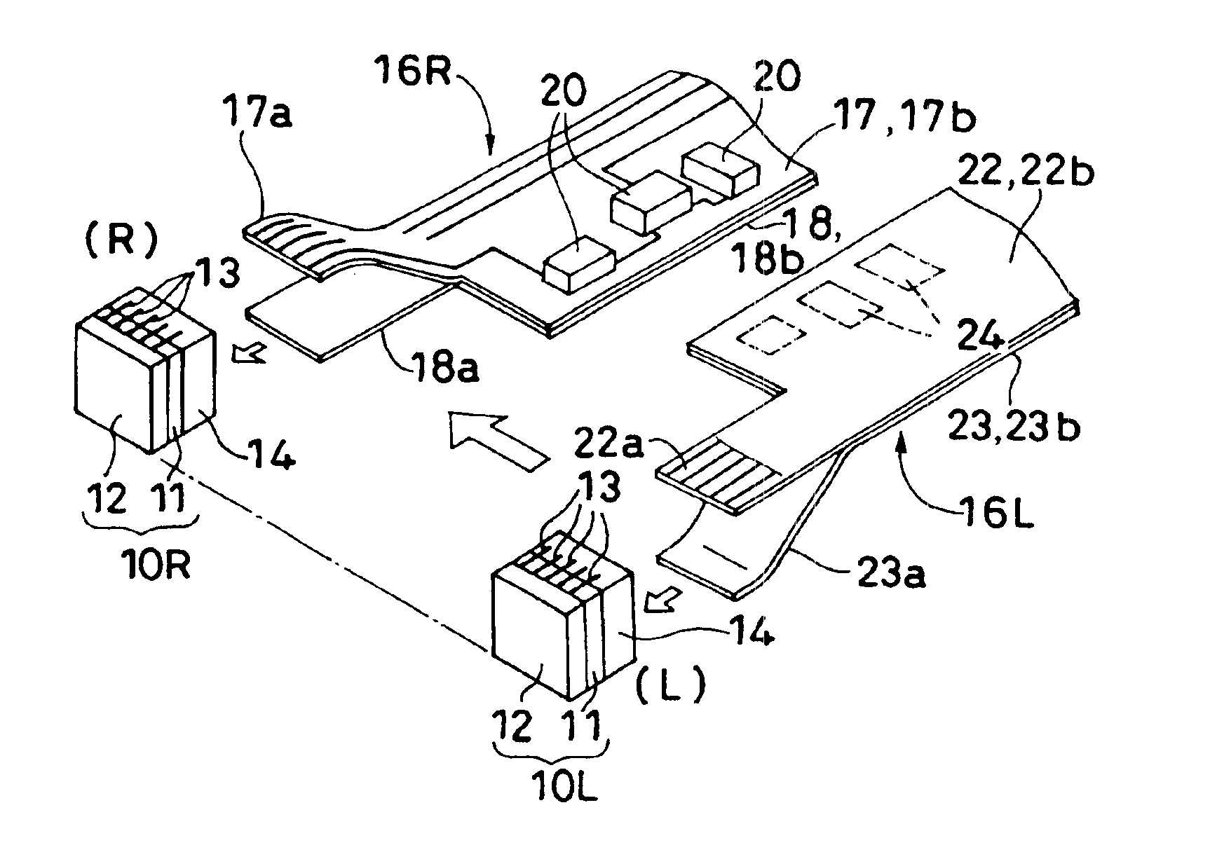
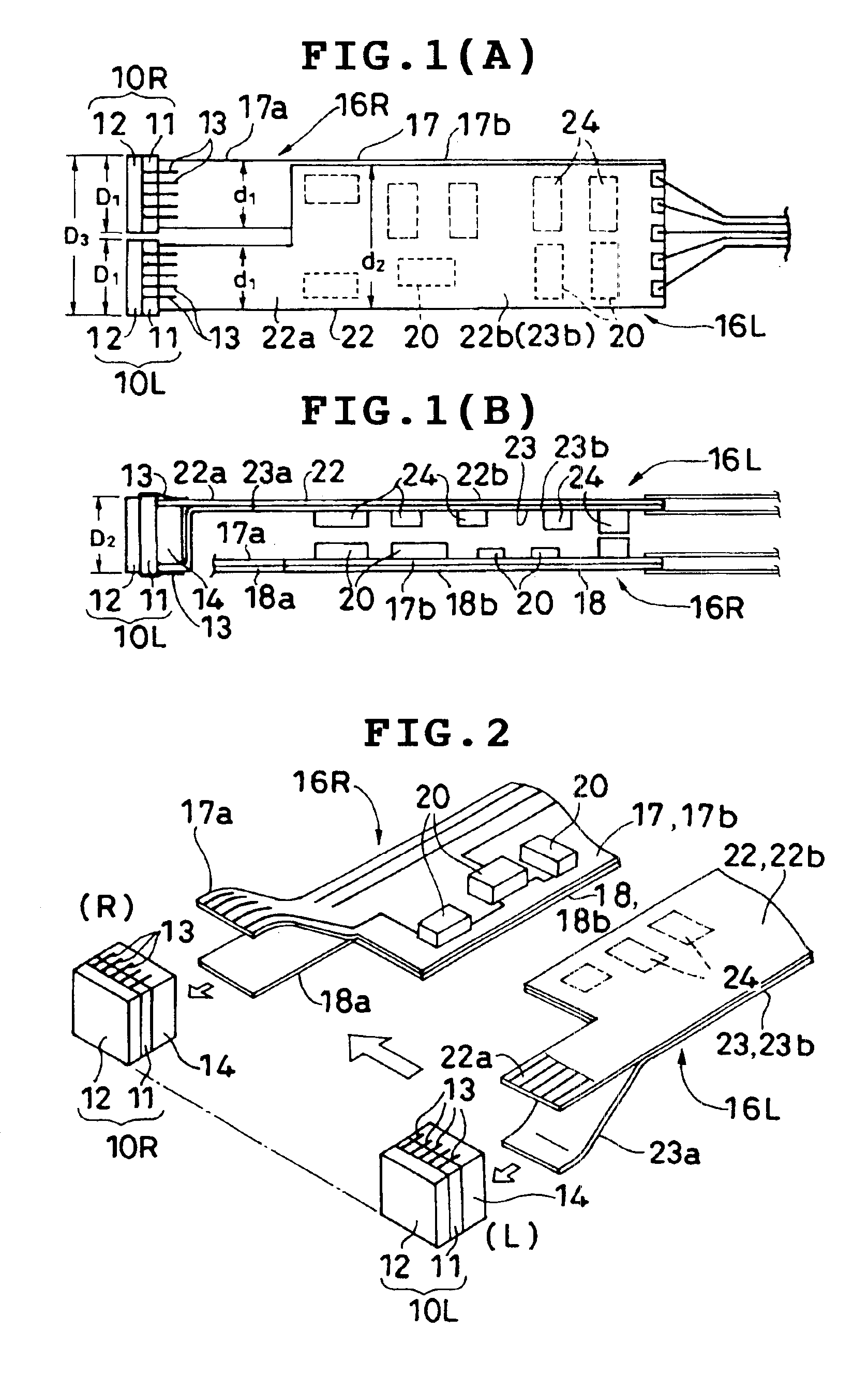
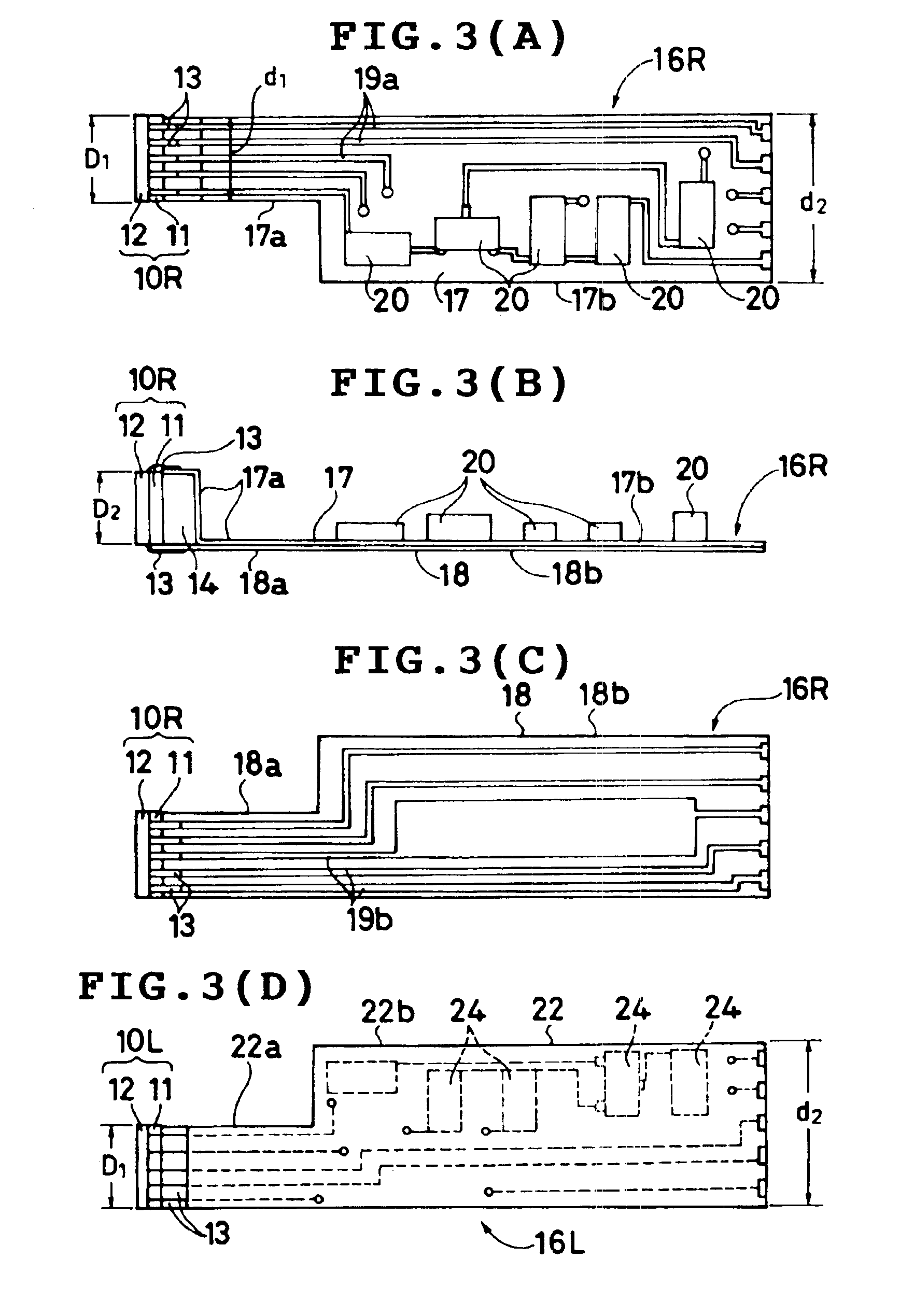
[0024]In the following description, parts or units which are not of direct importance to the invention and parts or units which are purely of conventional construction will not be described in detail. For example, the objective lens systems for forming right and left optical images of an object on the imaging device, the electronic control system for providing video signals, etc., necessary to the electronic stereoscopic endoscope system in which the imaging device assembly of the present invention is installed, will not set out since their construction and operation can easily be arrived at by those skilled in the art.
[0025]Referring now to the drawings in detail and, in particular, FIGS. 1(A), 1(B) and 2 showing a structure of an imaging device assembly according to a preferred embodiment of the present invention that is used for an electronic endoscope of an electronic stereoscopic endoscope system, the imaging device assembly basically comprises right and left image pick-up modu...
PUM
 Abstract
Description
Claims
Application Information