Alternating current generator

Inactive Publication Date: 2005-09-20
REARDON JOHN
View PDF10 Cites 4 Cited by
  • Summary
  • Abstract
  • Description
  • Claims
  • Application Information

AI Technical Summary

Benefits of technology

[0007]It is still another object of the present invention to provide an alternating current

Problems solved by technology

However, prior alternating current generators which employ rotating magnet systems are inefficie

Method used


Image

  • Alternating current generator
  • Alternating current generator
  • Alternating current generator

Examples


Embodiment Construction

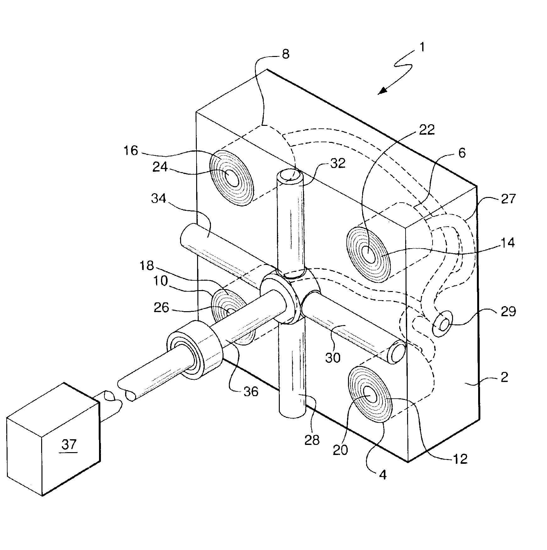
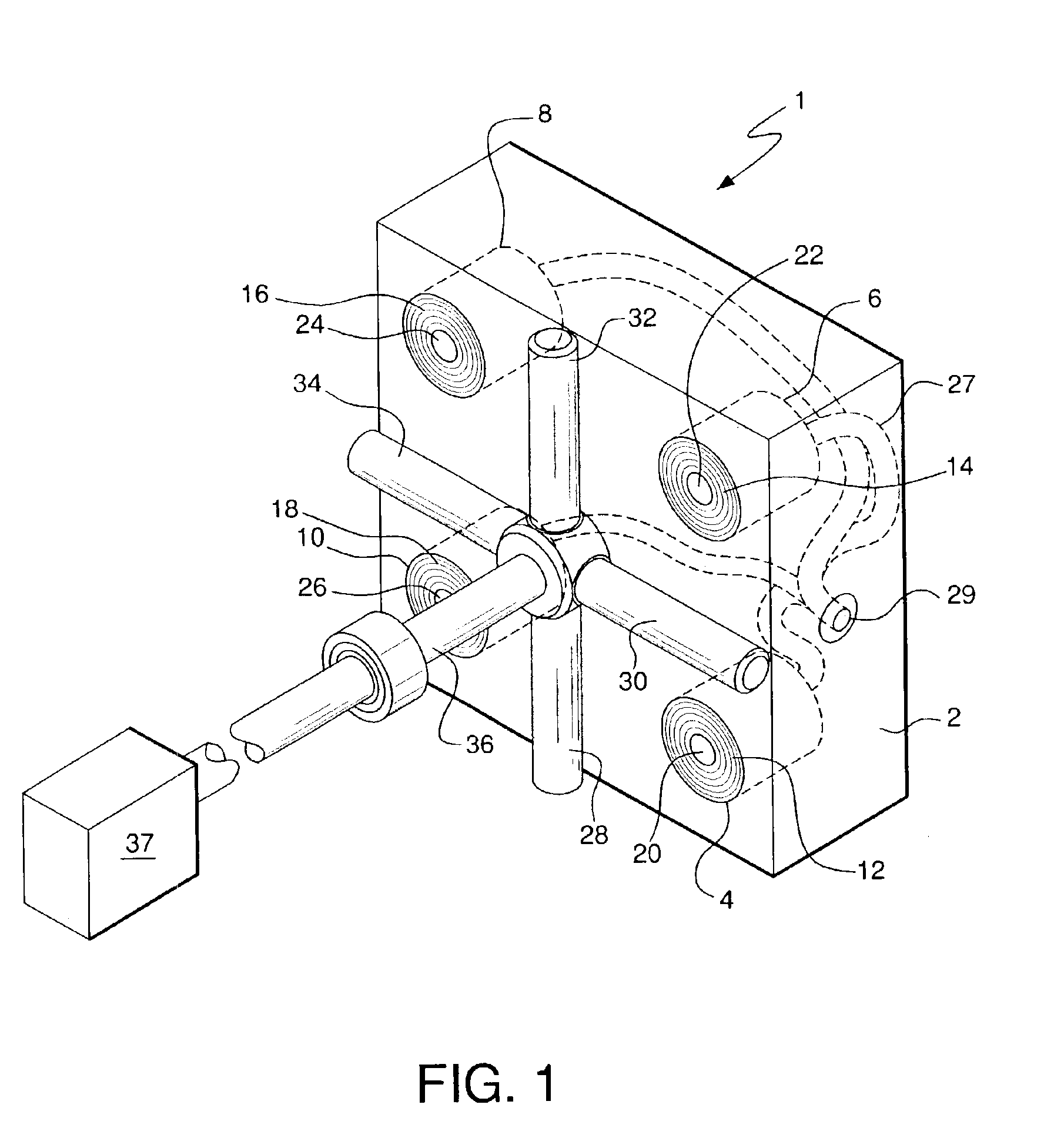
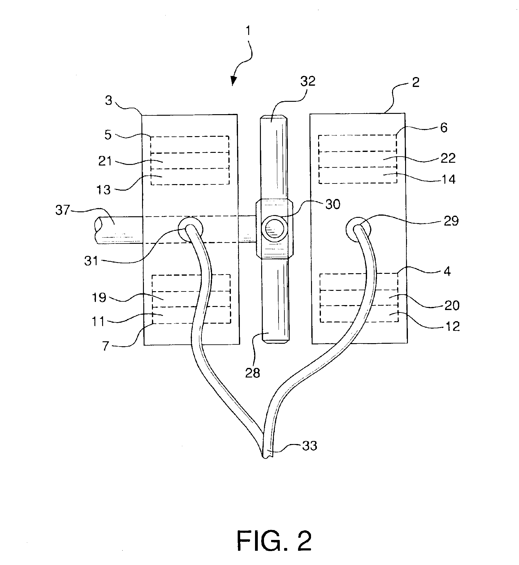
[0014]FIGS. 1 and 2 show a clear depiction of the components of alternating current generator 1 of the subject invention. Generator 1 comprises housings 2 and 3. For simplicity purposes and ease of understanding, only housing 2 is shown in FIG. 1. It must be understood, however, that generator 1 of the present invention is configured for use with both housings 2 and 3. Housing 2 contains coil elements 4, 6, 8 and 10. Each said coil element comprises multiple windings 12, 14, 16, and 18, respectively, wound around inner steel or similar metal cores 20, 22, 24, and 26, respectively. Each steel core extends the full length and directly through each of the coil elements. Coil elements 4, 6, 8, and 10 are mounted within housing 2, such that the end surfaces of the coil elements and the ends of cores 20, 22, 24, and 26 are positioned flush with the external surface of housing 2.

[0015]Housing 3 also contains four coil elements positioned identically as has been described with regard to hou...


PUM


Abstract

An alternating current electrical generator creates three different and distinct magnetic fields between would coil elements and rotating magnets, two fields of which are induced fields caused by magnet rotation. A plurality of magnets are positioned such that they extend outwardly from a rotating shaft. The magnets are circumferentially spaced around the shaft such that the north polar end of one magnet follows the south polar end of the next magnet or such that the polar end of one magnet follows a magnet with the same polar end. A plurality of stationary coil elements are positioned in spaced relation to the magnets. The coil elements each have electrical windings and metal cores which extend the lengths of the coil elements. The magnets rotate in spaced relation to the ends of the coil elements in such a way that the magnets' flux lines cut the cores located at the center of each of the coil elements. This induces alternating electric current that oscillates back and forth along the lengths of the cores. This oscillating current creates an expanding and collapsing set of magnetic flux lines which expand and contract through every inch of the coil element's windings. This expanding and collapsing magnetic field induces an expanding and collapsing magnetic field and an alternating electric field in the coil elements.

Description

BACKGROUND OF THE INVENTION[0001]Alternating current generators are rotating devices which convert mechanical energy into electrical energy. To generate an electromotive force by mechanical motion, there must be movement between an electric coil and a magnetic field in a manner that will cause a change in the flux that passes through the coil. Fundamentally, the induced electromotive force is brought about by a change in the flux passing through the coil.[0002]The use of electromagnets, magnets and magnet components in generators to create the magnetic field and its subsequent effect on electric coils to ultimately generate electric current is well known. Such magnetic generators operate by using the repelling forces created by the effect of changing polarities of both permanent and electromagnets. For instance, there are electrical generating devices which employ electromagnets which are fixed in position and which induce current by being selectively energized, as iron or other mag...

Claims


Application Information

Patent Timeline
IPC IPC(8): H02K21/12H02K21/14H02K21/24H02K53/00
CPCH02K21/145H02K21/24H02K53/00
Inventor REARDON, JOHN
Owner REARDON JOHN
Why Eureka
Try Eureka