Protective device for an electric motor with sensor and evaluation unit

a technology of protection device and electric motor, which is applied in the direction of motor/generator/converter stopper, dynamo-electric converter control, instruments, etc., can solve the problems of winding voltage breakdown, damage to the involved components, and operator risk in view of vagabond voltage that may reach the operating elements

Inactive Publication Date: 2005-09-20
SIEMENS AG
View PDF6 Cites 18 Cited by
  • Summary
  • Abstract
  • Description
  • Claims
  • Application Information

AI Technical Summary

Benefits of technology

[0008]According to another feature of the present invention, the isolation element may be an isolation transformer having two windings, wherein one winding is connected to the signal input, and the other winding is connected to the signal output. In this way, the two windings are securely isolated from one another even at highest voltages to be expected. The sensor-side winding is so dimensioned as to consume only very little power and overvoltage of the sensor will not result in a damage of the insulation to the other winding. The isolation transformer may be constructed in a compact design and at a safe distance to the element to be monitored by the sensor, e.g. a motor winding.
[0011]According to another aspect of the present invention, a sensor assembly includes a sensor, an evaluation unit, and a protective device having a signal input for connection to the sensor, a signal output for connection to the evaluation unit, and an isolation element for galvanically isolating the signal input from the signal output, wherein the sensor is a temperature sensor. Suitably, the sensor has a linear characteristic or a switching characteristic. The evaluation unit monitors hereby a signal from the sensor and outputs a machine shutdown command, when the sensor signal indicates a hazardous level during a predetermined time interval or at two points in time which are separated by a predetermined time interval. In this way, a situation is avoided in which the sensor signal shuts down the machine each time there is a momentary fluctuation.

Problems solved by technology

However, localized fire or a meltdown of the insulation may be encountered when the windings are short-circuited, so that the winding voltage may breakdown via the sensor to the evaluation unit or transducer card.
Not only may this lead to a destruction of the involved components but there is also a risk to an operator in view of vagabond voltage that may reach the operating elements.
This is disadvantageous because the sensor reacts very sluggishly to temperature fluctuations so that a rapid temperature increase cannot be detected with sufficient speed.
As these devices are relatively bulky and typically operate at a voltage of 230 V, they are normally mounted in a switch cabinet or to the inverter of the motor.

Method used


Image

  • Protective device for an electric motor with sensor and evaluation unit
  • Protective device for an electric motor with sensor and evaluation unit

Examples


Embodiment Construction

[0014]The depicted embodiment is to be understood as illustrative of the invention and not as limiting in any way.

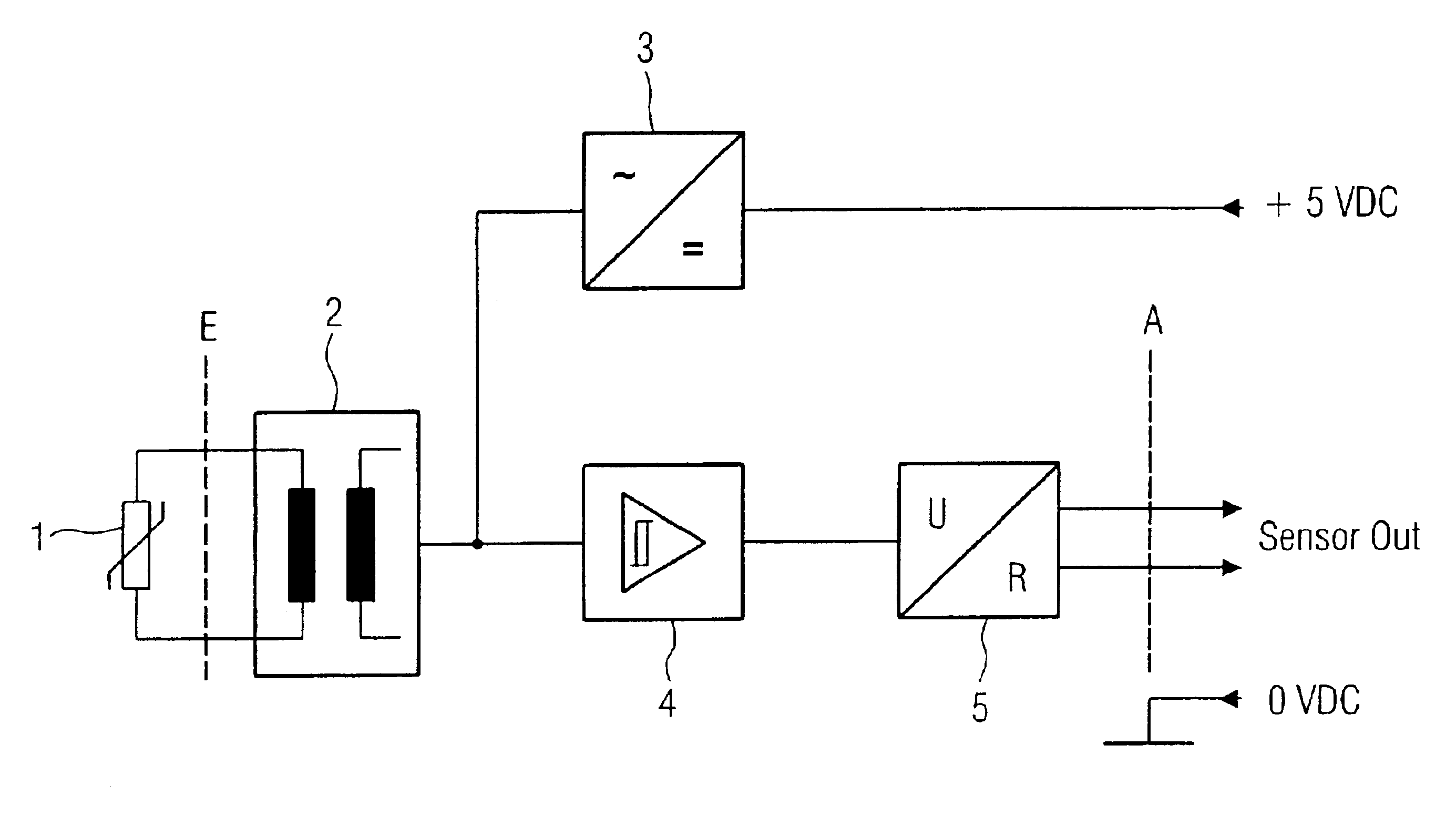
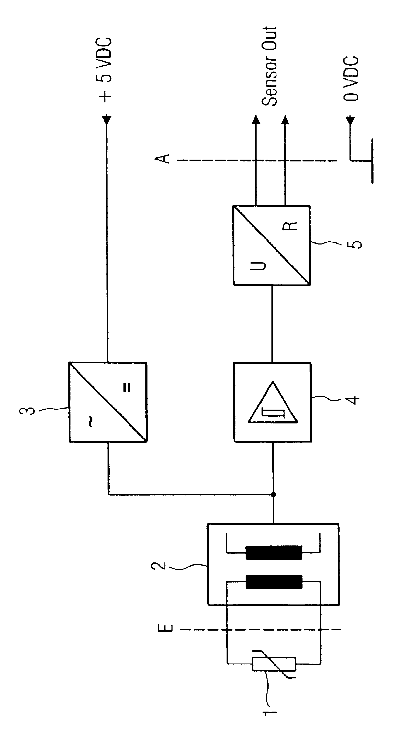
[0015]Turning now to FIG. 1, there is shown a schematic circuit diagram of a protective device according to the present invention for providing a protection from overvoltage generated by a sensor 1 which may be part of an electric motor, e.g., an electric linear motor or electric rotary motor. The protection device includes an isolation element such as an isolation transformer 2 having two windings, with one winding connected to a sensor 1, preferably a temperature-dependent resistor, and the other winding connected to an oscillator 3. Construction of such an isolation transformer is generally known to the artisan so that a detailed description thereof is omitted for the sake of simplicity.

[0016]The oscillator 3 is fed with a d.c. voltage of, for example, 5 volts and converts the d.c. voltage into an a.c. voltage with a carrier frequency.

[0017]When the resistance value o...


PUM


Abstract

A protective device includes a signal input intended for connection to a sensor, a signal output intended for connection to an evaluation unit, and an isolation element for galvanically separating the signal input from the signal output. The provision of the protective device prevents a transmission of overvoltages from the sensor to the evaluating unit.

Description

CROSS-REFERENCES TO RELATED APPLICATIONS[0001]This application claims the priority of German Patent Application, Serial No. 101 64 204.0, filed Dec. 27, 2001, pursuant to 35 U.S.C. 119(a)-(d), the disclosure of which is incorporated herein by reference.BACKGROUND OF THE INVENTION[0002]The present invention relates, in general, to a protective device, and more particularly to a protective device for, for example, an electric motor of a type having a main body, which carries windings, and at least one sensor, which is arranged as passive motor element upon a winding and outputs electric signals to an evaluation unit.[0003]An example of a sensor includes a temperature sensor which is embedded in the windings and is monitored by an evaluation unit or transducer card to ascertain or prevent inadmissibly high temperatures. Operating voltages for the sensor or the transducer card are typically in the range of safety low voltages of about 5 V to 24 V. On the other hand, there are motors for...

Claims


Application Information

Patent Timeline
Patent Type & Authority Patents(United States)
IPC IPC(8): H02H1/00H02P29/02H02H7/085
CPCH02H1/0007H02P29/02H02H7/0852
Inventor KLAUS, MAXIMILIANMATSCHEKO, GERHARD
Owner SIEMENS AG
Why Eureka
Try Eureka