
Tuner block for use in video signal receiving apparatus having modulator, tuner and IF/demodulator circuit

a video signal and receiving apparatus technology, applied in the direction of continuous tuning, television systems, instruments, etc., can solve the problems of unnecessarily unnecessary noise and interference, and unnecessary large size of conventional tuner blocks b>50/b>, so as to minimize noise and interference generation and simplify circuit construction in the casing

Inactive Publication Date: 2005-09-20
SAMSUNG ELECTRONICS CO LTD
View PDF14 Cites 7 Cited by
  • Summary
  • Abstract
  • Description
  • Claims
  • Application Information

AI Technical Summary

Benefits of technology

[0019]A second object of the present invention is to provide a tuner block comprising an integrally formed modulator and IF / demodulator circuit, which realizes a compact casing and simplifies circuit construction in the casing, by determining positions of the pins in consideration of a position of a modulator IC and an integrated tuner and IF / demodulator circuit IC disposed in the casing.
[0020]A third object of the present invention is to provide a tuner block comprising an integrally formed modulator and IF / demodulator circuit, which creates a compact casing and minimizes the generation of a noise and interference between signals due to the compact casing.
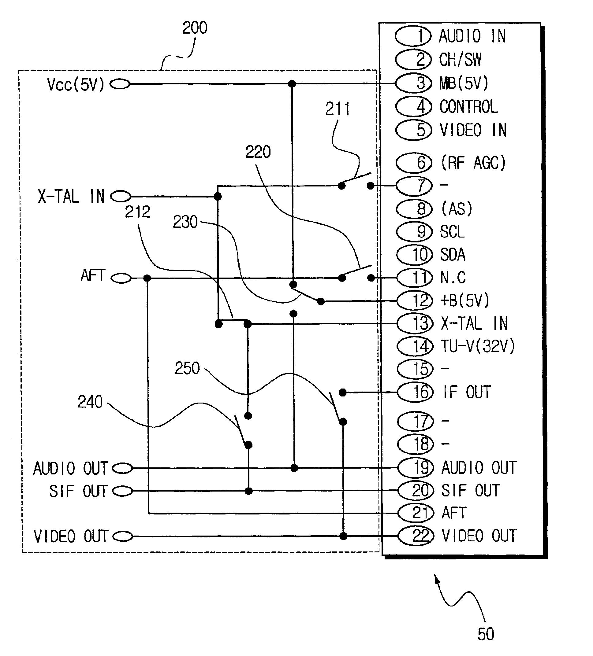
[0023]Here, one of the plurality of pins is a power supply pin through which an electrical power is supplied from an outside power supply. The tuner and the modulator are commonly connected to the power supply pin at an inside of the casing, whereby the tuner and the modulator are supplied with the electrical power required for a normal operation thereof through the power supply pin. Since the modulator and the tuner are supplied from a common pin, the number of the pins is reduced and a tuner block may be manufactured which is smaller in size compared with the conventional tuner block.
[0032]Accordingly, the pins are disposed to correspond to the position of the modulator IC and the integrated tuner and IF / demodulator IC installed in the casing. Therefore, the compact tuner block may be realized and at the same time, a circuit construction in the casing is simplified. Furthermore, interference between the signals and the noise is minimized in the compact tuner block.

Problems solved by technology

For example, where the video output pin and the audio output pin are closely disposed, the video output signal causes interference to the audio output signal, thus noise is added to the audio signal.
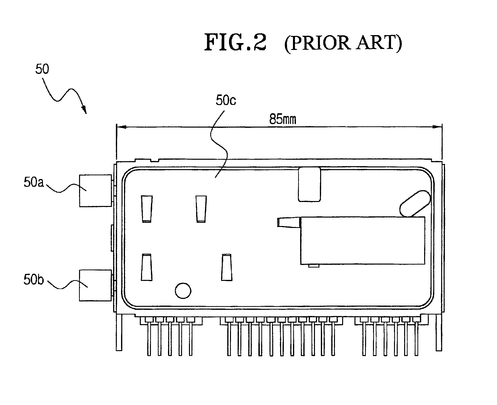
However, a size of the conventional tuner block 50 becomes unnecessarily large since more pins are disposed than the number of pins actually needed for the broadcasting signal receiving apparatus.
Yet, the conventional tuner block 50 has the pins that are not used, thus the size of the tuner block 50 becomes unnecessarily large.
Thus, it is difficult to realize a compact broadcasting signal receiving apparatus because of the unnecessarily large tuner block 50.
Therefore, to move some of the used pins to the position of the unused pins (pin 7, 11, 15, 17, 18) to reduce the number of the pins complicates construction of a circuit that connects the modulator IC and the integrated tuner and IF / demodulator circuit IC in the casing 50c and increases a probability that noise caused by the signal interference will be generated.

Method used


Image

  • Tuner block for use in video signal receiving apparatus having modulator, tuner and IF/demodulator circuit
  • Tuner block for use in video signal receiving apparatus having modulator, tuner and IF/demodulator circuit
  • Tuner block for use in video signal receiving apparatus having modulator, tuner and IF/demodulator circuit

Examples


Embodiment Construction

[0042]Reference will now be made in detail to the present embodiments of the present invention, examples of which are illustrated in the accompanying drawings, wherein like reference numerals refer to like elements throughout.

[0043]FIG. 4 is a view showing the appearance of a tuner block comprising a modulator and an IF / demodulator circuit according to the present invention. The tuner block 150 comprises a modulator, a tuner, an IF / demodulator circuit and a casing 150c which accommodates the modulator, the tuner, and the IF / demodulator circuit. An antenna input terminal 150a and an antenna output terminal 150b are installed at an outside of the casing 150c. A modulator IC is disposed at an adjacent position to the antenna input terminal 150a and the antenna output terminal 150b in the casing 150c. An integrated tuner and IF / demodulator circuit IC is disposed at a distant place from the position of the modulator IC.

[0044]Sixteen pins are disposed at a side of the casing 150c. The phy...


PUM


Abstract

A tuner block in which a modulator and an IF / demodulator circuit are integrally formed. The tuner block has a casing for accommodating a tuner, the IF / demodulator circuit and the modulator, and sixteen pins consecutively disposed at an outside of the casing. A number of the pins is reduced as compared with a conventional tuner block by supplying an electrical power to the modulator and the tuner through a common pin, dispensing with pins carrying unnecessary signals and pins which carry no signal and rearranging other pins. Potential for noise and interference between signals is reduced by maximizing displacements of connector pins which carry signals which are likely to interact. A switching arrangement provides for utilizing either a conventional tuner block or a tuner block according to the present invention on a circuit board.

Description

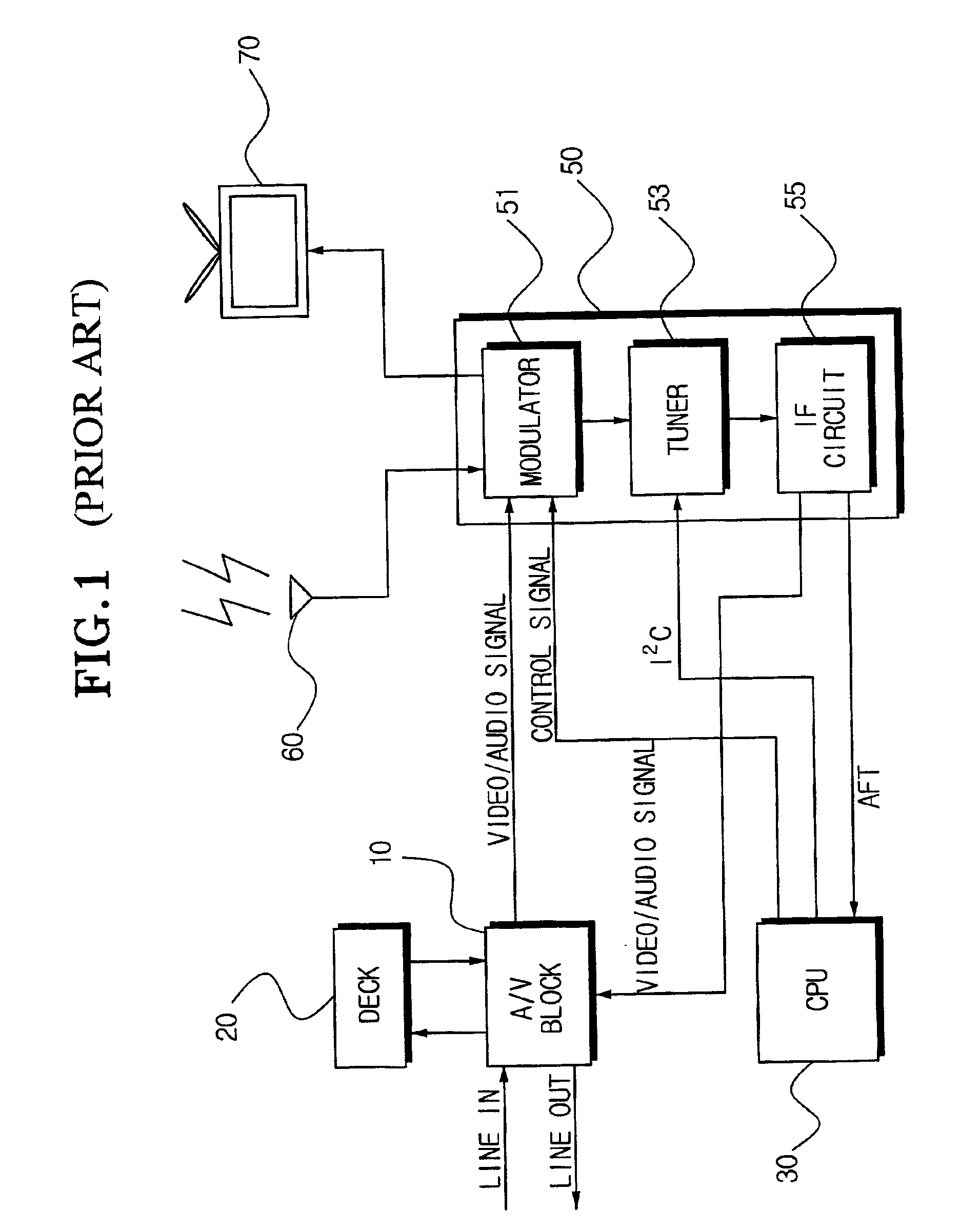
CROSS REFERENCE TO RELATED APPLICATIONS[0001]This application claims the benefit of Korean Application No. 2001-62462 filed Oct. 10, 2001, in the Korean Patent Office, the disclosure of which is incorporated herein by reference.BACKGROUND OF THE INVENTION[0002]1. Field of the Invention[0003]The present invention relates to a tuner block for a broadcasting signal receiving apparatus such as a VCR, and more particularly, to a tuner block having a modulator, a tuner and IF / demodulator circuit which are built integrally in a casing.[0004]2. Description of the Related Art[0005]As shown in FIG. 1, a broadcasting signal receiving apparatus such as a VCR comprises an A / V block 10 for processing a video signal and an audio signal, a deck 20 for recording / reproducing the video signal and the audio signal on / from a recording medium such as a magnetic tape, a tuner block 50 for demodulating the video signal and the audio signal from the broadcasting signal transmitted through an antenna 60, and...

Claims


Application Information

Patent Timeline
IPC IPC(8): H04N5/775H04N5/64H04N5/782H04N5/50
CPCH04N5/64H04N21/4263H04N5/782H04N5/7755H04N5/50
Inventor KIM, CHUL-MINYOO, SEUNG-BONGSUH, YONG-BUM
Owner SAMSUNG ELECTRONICS CO LTD
Learn More