
Valve mounting assembly for voice prosthesis-cartridge and ring

a technology for voice prosthesis and mounting assembly, which is applied in the direction of prosthesis, tracheae, functional valve types, etc., can solve the problems of high percentage of prosthesis, difficult manipulation, and inability to provide a secure and reliable attachment of the valv

Inactive Publication Date: 2005-09-27
FREUDENBERG MEDICAL
View PDF6 Cites 41 Cited by
  • Summary
  • Abstract
  • Description
  • Claims
  • Application Information

AI Technical Summary

Benefits of technology

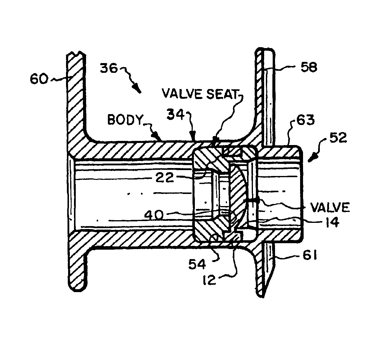
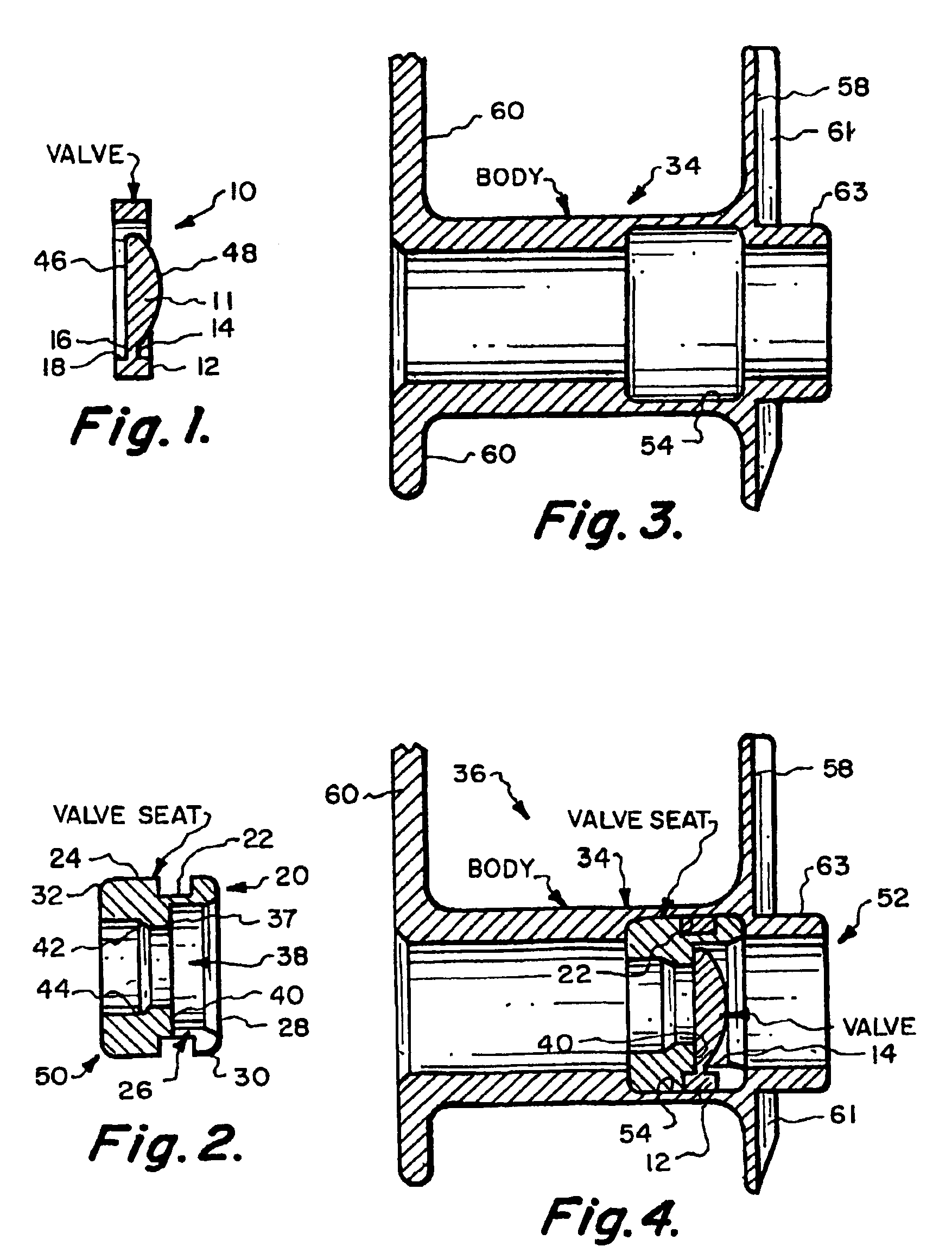
[0015]The valve mounting system of the invention is easy to manipulate and install. The valve mounting system reliably seats the valve in correct position. Adhesive is not necessary to achieve reliable and long term functioning of the valve. The valve mounting system of the invention incorporates a hard cartridge with a groove on its outer, distal surface and a slot communicating distal from the end of the cartridge with the groove and a specially configured elastomeric valve attached to an outer band with a short tab. The band is positioned with the tab designed with the slot and is stretched and slid proximally over the cartridge until the tab enters the slot and the band snaps into and seats in the groove. The width of the slot is the same as the width of the tab providing exact alignment of the valve element with the seat provided in the cartridge. The tab can be disposed at an angle to the seat to preload the valve element against the seat.
[0017]The valve may optionally be dome-shaped to provide further strengthening of the valve and to assure that it will not distort and leak even when encrusted with a layer of yeast.

Problems solved by technology

Though the ring stiffens the body adjacent the valve does not prevent distortion of the body by muscular movement or distortion of the valve by growth of yeast.
This is a labor intensive step and the thin segment does not provide a secure and reliable attachment of the valve to the prosthesis.
They are difficult to manipulate.
Correct seating of the tab in the slot is not reliable resulting in a high percentage of prosthesis in which the valve does not seal when in the closed position and must be discarded.

Method used


Image

  • Valve mounting assembly for voice prosthesis-cartridge and ring
  • Valve mounting assembly for voice prosthesis-cartridge and ring
  • Valve mounting assembly for voice prosthesis-cartridge and ring

Examples


Embodiment Construction

[0032]Referring now to FIGS. 1-4, FIG. 1 illustrates an elastomer flapper valve 10 formed of a valve element 11 spaced from and connected to a surrounding mounting band 12 by a tab 14 extending from the outer surface 16 of the valve element to inner surface 18 of the band 12. The rigid cartridge 20 shown in FIG. 2 has a groove 22 formed in the outer surface 24 and a slot 26 formed in the distal surface 28 extending from the distal surface 28 to the groove 22. The width of the slot 26 is coextensive with the width of the tab 14. The outer edges of the distal surface 28 is rounded at 30 to prevent tearing of the mounting band 12 as it is assembled with the cartridge 20. The outer edge 32 of the proximal surface of the cartridge 20 can also be chamfered or rounded to prevent tearing of the soft body 34 of the voice prosthesis 36.

[0033]The cartridge 20 contains a boss 37 extending into the channel 38 through the cartridge forming on its distal surface a seat 40 for the valve element 11....


PUM


Abstract

The valve mounting system of the invention incorporates a hard cartridge with a grove on its outer, distal surface and a slot communicating distal from the end of the cartridge with the grove and a specially configured elastomeric valve attached to an outer band with a short tab. The band is positioned with the tab aligned with the slot and is stretched and is slid proximally over the cartridge until the tap enters the slot and the band snaps into the seats in the groove. The width of the slot is the same as the width of the tab providing exact alignment of the valve element with the seat provided in the cartridge. The tab can be disposed at an angle to the seat to preload the valve element against the seat.

Description

[0001]This application claims the benefit of Provisional Application No. 60 / 344,444 filed Dec. 28, 2001.TECHNICAL FIELD[0002]This invention relates to a voice prosthesis and more particularly this invention relates to a mounting assembly for a valve.BACKGROUND OF THE INVENTION[0003]There are several options for restoring speech to patients who have had their larynx removed. One procedure is to surgically create a puncture or fistula between the tracheal and the esophagus. A trachea voice prosthesis containing a one-way valve such as a BLOM-SINGER® voice prosthesis is inserted into the trachea-esophageal fistula. The one-way valve protects the airway during swallowing but opens under positive pressure. The voice prosthesis, thus, permits a patient to divert air from the lungs into the esophagus and out through the mouth. Speech is created during passage of air through the upper part of the esophagus.[0004]The prosthesis maintains the fistula open, transfers air from the trachea to th...

Claims


Application Information

Patent Timeline
IPC IPC(8): A61F2/20
CPCA61F2/203A61M16/0468Y10T137/7898Y10T137/7891F16K15/16F16K15/031
Inventor SEDER, EDMUND V.PORTER, TINA
Owner FREUDENBERG MEDICAL
Learn More