Ink container, inkjet printing apparatus and ink supplying method

a technology of inkjet printing and ink, which is applied in the field of ink supply methods, ink supply methods, ink supply containers, etc., can solve the problems of difficult to make the apparatus as a whole compact, inability to design such printers in adaptation, and limited capacity of ink tanks, etc., to achieve easy maintenance of ink endurance, short charging time, and high charging efficiency

Inactive Publication Date: 2005-09-27
CANON KK
View PDF16 Cites 34 Cited by
  • Summary
  • Abstract
  • Description
  • Claims
  • Application Information

AI Technical Summary

Benefits of technology

[0022]The invention was made taking the above problems into consideration, and it provides a structure in which an intermittent supply system is adopted as an ink supply system; waste of ink such as generation of waste ink associated with a charging operation will not fundamentally occur; high charging efficiency and a short charging time is achieved; and endurance of ink can be easily maintained, i.e., a structure with which freedom in selecting ink can be increased.

Problems solved by technology

Therefore, only an ink tank having a very limited capacity can be used when a small-sized printing apparatus, especially, a portable printing apparatus is to be formed.
This results in very frequent replacement of the printing head integral with the ink tank or the ink tank alone, which has been problematic from the viewpoint of operability and running cost.
It is considered impractical to design such printers in adaptation to the on-carriage method.
When a tube supply type structure is adopted, although members that move with a carriage during main scanning can be made compact to some degree, it is difficult to make the apparatus as a whole compact because a space is required for a tube member to move to follow up the carriage, the tube member coupling a printing head on the carriage and an ink tank located outside the carriage to supply ink.
Further, the recent trend is that a carriage is scanned at a high speed to accommodate increases in the speed of printing operations, and resultant severe rocking of a tube that follows the carriage results in changes in the pressure of ink in an ink supply system for the printing head.
It is therefore required to provide various complicated pressure buffering mechanisms in order to suppress pressure changes, it has been difficult to achieve a size reduction in this respect too.
The entrance of a gas is a problem that inevitably occurs, although the amount of the gas varies depending on the structure of the supply system.
When a gas is accumulated in a second ink tank on a carriage for example, a problem arises in that the efficiency of charging the second ink tank with ink is reduced accordingly.
Further, unexpected pressure changes are caused by expansion and contraction of air in response to temperature changes.
This can result in leakage of ink from ejection openings attributable to an action of a resultant excessively large positive pressure or can conversely result in a failure of ink ejection attributable to an action of an excessively large negative pressure.
Furthermore, the gas accumulated in the second ink tank can be included in ink that is guided to the ejection openings to cause problems such as disablement of ink ejection.
Such problems can be similarly caused when a continuous supply system of the tube supply type is configured.
Since a great amount of waste ink is generated as a result of the adoption of such measures, serious limits are put on designing when a compact and portable printing apparatus is to be provided using the intermittent supply method.
In addition, since it is also required to perform a wiping operation for removing ink deposited on the surface of the printing head having the ejection openings formed thereon as a post-process for the recovery operation and a preliminary ejecting operation, a problem arises in that a further time is spent accordingly.
This puts a limit on even the position and attitude or orientation of the ink tank and has resulted in problems including leakage of ink from the ejection openings especially in case that a portable printing apparatus is to be provided which is unstable in attitude during transportation.
However, in order to use the functional film with stability, it is required that the film stays in a chemically inert state for a long time, which has resulted in a problem in that freedom in selecting ink is reduced, e.g., ink having a composition that does not affect the functional film must be selected.
When a negative pressure generating mechanism such as a porous member for keeping ink under a negative pressure relative to a nozzle of the printing head is provided in the second ink tank for this reason, the efficiency of containing ink in the second ink tank is limited.
Designing may be limited with respect to deposition of dyes and pigments in ink and endurance of the porous member against deterioration, which also reduces alternatives and freedom in selecting ink.
That is, a problem arises in that a charging operation is accompanied by the generation of waste ink.

Method used


Image

  • Ink container, inkjet printing apparatus and ink supplying method
  • Ink container, inkjet printing apparatus and ink supplying method
  • Ink container, inkjet printing apparatus and ink supplying method

Examples


Embodiment Construction

[0076]The invention will now be described in detail with reference to the drawings.

(Example of Structure of Inkjet Printing Apparatus)

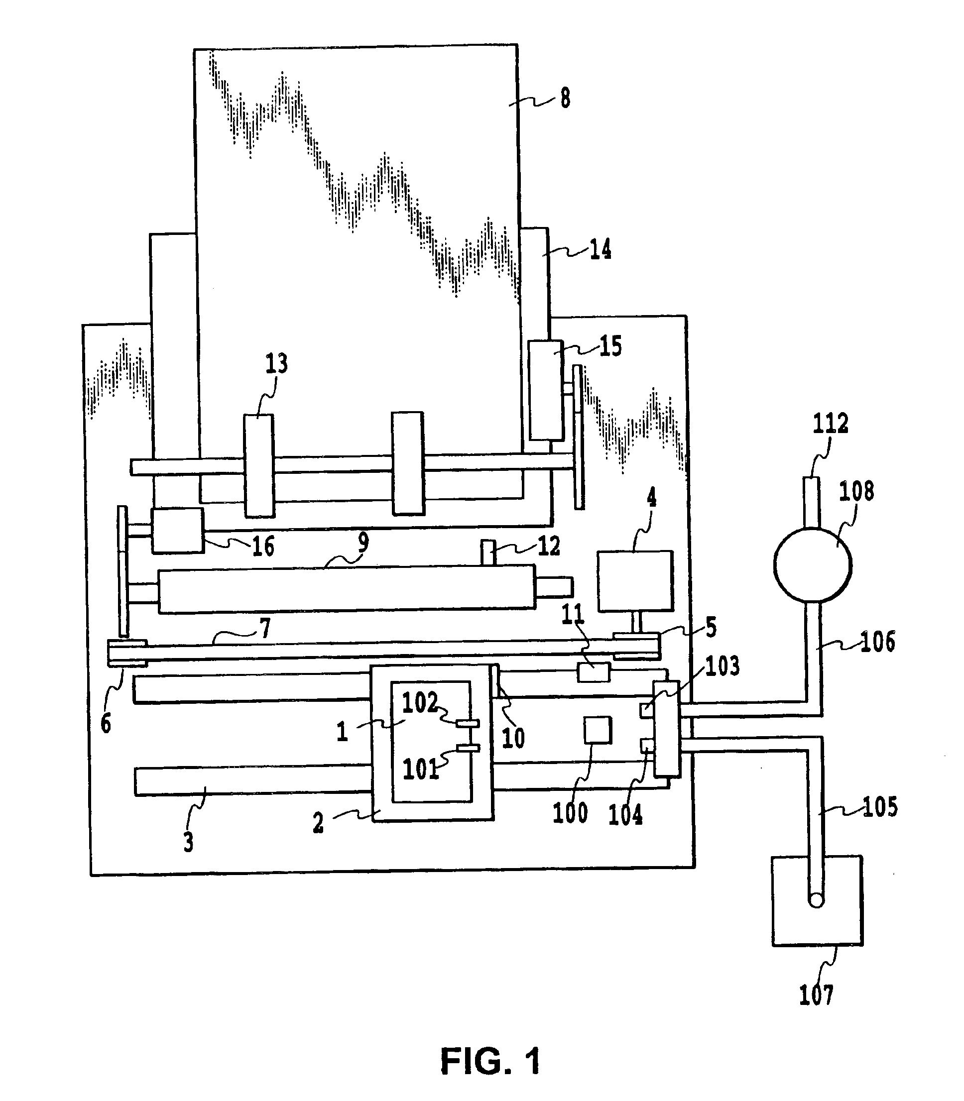
[0077]FIG. 1 is a schematic plan view showing a general structure of an inkjet printing apparatus utilizing an intermittent supply system according to an embodiment of the invention.

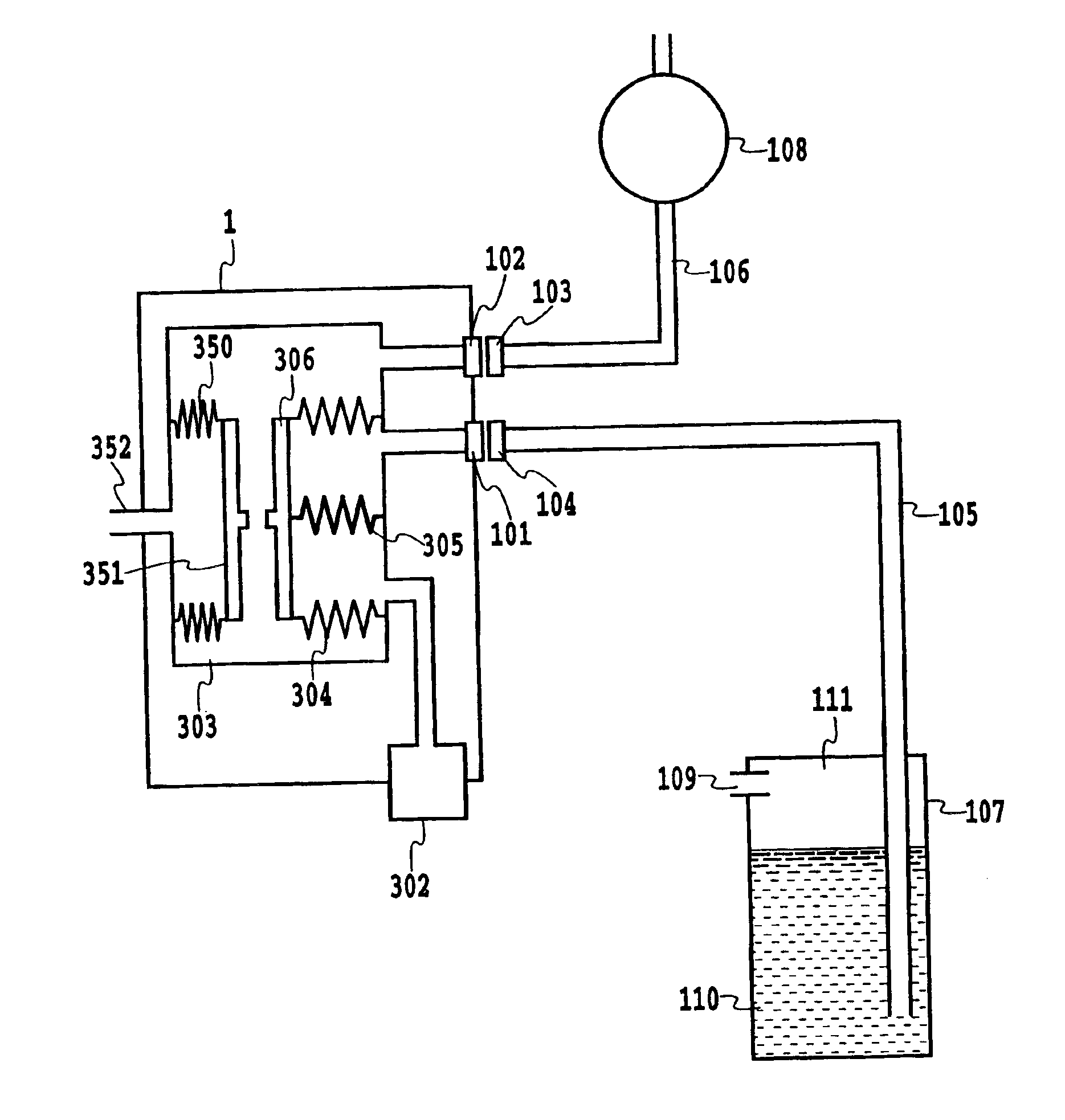
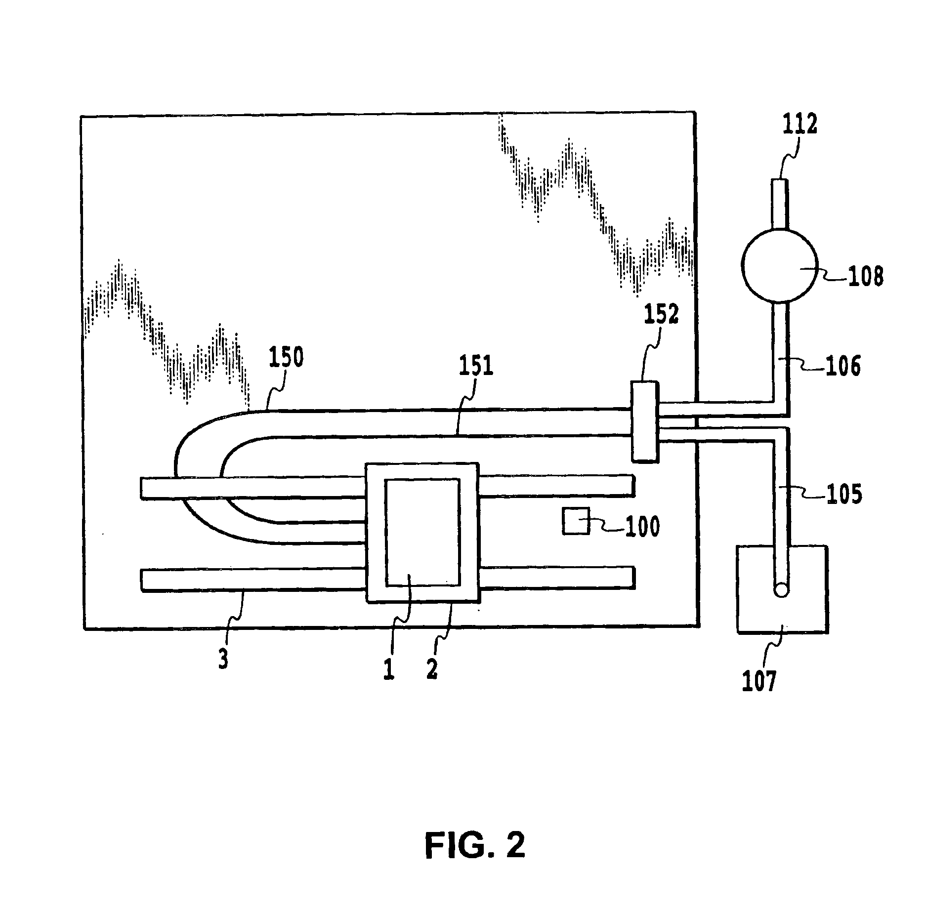
[0078]In the structure in FIG. 1, a printing head unit 1 is replaceably mounted on a carriage 1. The printing head unit 1 has a printing head section and a second ink tank section, and there is provided a connector (not shown) for transmitting signals such as a drive signal for driving the head section to cause an ink ejecting operation of a nozzle. The carriage 2 on which the printing head unit 1 is positioned and replaceably mounted is provided with a connector holder (electrical connecting section) for transmitting signals such as the drive signal to the printing head unit 1 through the connector.

[0079]The carriage 2 is guided and supported by a guide shaft 3 provided o...


PUM


Abstract

For eliminating waste of ink and achieving high charging efficiency with a reduced charging time where a printing head is equipped with a second tank for reserving a predetermined amount of ink and a supply system is configured to supply ink from a first tank to the second tank intermittently, the second tank is provided with a variable internal volume. The internal volume is varied to cause the second tank itself to function as an actuator for charging ink and performing a venting process. Specifically, the internal volume is forcibly reduced to cause a reverse flow of a gas residing in the second tank along with ink into the first tank, which makes it possible to generate of waste ink that is released to the outside. A normal charging operation can be completed simply by causing a change in the opposite direction (the direction of increasing the internal volume). Relatedly, the second tank may be provided with a member for holding ink and generating a negative pressure originating from an elastic force. With connection of the first tank and the member, the pressure in the second tank is reduced to cause the member to expand, thereby introducing ink into the same. This introduction is stopped by regulating the expansion with a displaceable unit which expands when the pressure is reduced. The regulation is performed at such a position that the negative pressure generated in the member by canceling regulation is in equilibrium with an ink meniscus-holding ability of the printing head.

Description

CROSS-REFERENCE TO RELATED APPLICATIONS[0001]This application is a continuation-in-part of U.S. application Ser. No. 10 / 171,649 now abandoned, and a continuation-in-part of U.S. application Ser. No. 10 / 171,629 now abandoned, and a continuation-in-part of U.S. application Ser. No. 10 / 171,648 now abandoned, all filed Jun. 17, 2002, the contents of which are incorporated herein by reference.[0002]This application is based on Japanese Patent Application Nos. 2001-183740, 2001-183742, 2001-183743, all filed Jun. 18, 2001 in Japan, the contents of which are incorporated herein by reference.BACKGROUND OF THE INVENTION[0003]1. Field of the Invention[0004]The present invention relates to an ink container, an inkjet printing apparatus, a printing head, and an ink supplying method and, more particularly, the invention is preferably applied to an inkjet printing apparatus in which ink is intermittently supplied to a printing head for ejecting ink.[0005]2. Description of the Related Art[0006]Ink...

Claims


Application Information

Patent Timeline
Patent Type & Authority Patents(United States)
IPC IPC(8): B41J2/175
CPCB41J2/175B41J2/17509B41J2/17513B41J2/17556
Inventor YOSHIDA, MASAHITOOTSUKA, NAOJIINOUE, HIROYUKINOJIMA, TAKASHISUGIMOTO, HITOSHIINAMURA, SHUSUKETANAAMI, YASUFUMIIWASAKI, TAKESHISATO, NORIKOHIRAI, YASUYUKIYAZAWA, TAKESHI
Owner CANON KK
Why Eureka
Try Eureka