Vortex-induced vibration reduction device for fluid immersed cylinders

a technology of vibration reduction device and fluid immersion cylinder, which is applied in the direction of mechanical equipment, pipe laying and repair, drilling pipes, etc., can solve the problems of reducing affecting the service life of the riser, etc., to reduce the vibration of the vortex. induced, the effect of reducing the cost of fabrication

Inactive Publication Date: 2005-09-27
TECH FRANCE SA
View PDF14 Cites 37 Cited by
  • Summary
  • Abstract
  • Description
  • Claims
  • Application Information

AI Technical Summary

Benefits of technology

[0009]The present invention disclosed herein comprises a device, mechanism and method for use in a generally cylindrical assembly that is resistant to vortex-induced vibration when immersed in a moving fluid. The generally cylindrical assembly of the present invention, and particularly in the case of a cylindrical riser assembly, is easy to transport, handle and install and is not costly to fabricate. In addition, a feature of one embodiment of a cylindrical assembly according to certain inventive aspects of the present invention is that the cylindrical assembly is submergible in a body of water and resists or reduces vortex-induced vibration (VIV) and does not significantly increase the viscous drag of the fluid or water moving past the cylindrical assembly.
[0010]The vortex induced vibration (VIV) reduction mechanism of the present invention and the submergible cylindrical assembly of the present invention having such VIV reduction mechanism combined therewith effectively reduce the adverse effect of vortex-induced vibration when positioned in a flowing body of fluid such as water. The VIV reduction mechanism comprises a generally cylindrical column having a central axis, an outer surface, a wall thickness and a length. A pattern is cut or formed into the outer surface of the generally cylindrical column to selectively decrease the distance of the outer surface from the central axis. The pattern may be formed with a plurality of columnar sections each having a notch cut into the outer surface. A plurality of columnar sections are placed in series or stacked along the length of the cylindrical column. The notch of each columnar section is positioned in a selected circumferential angular relationship with the notch of each other columnar section and extends partially along the length of the column, thereby selectively reducing the thickness of the wall and producing a discontinuity in the outer cylindrical surface at selected positions. The angular position of each notch or of each reduced thickness portion of a wall around the circumference of the generally cylindrical column sections is differently selected along the length of the column. The selected angular positions provide a pattern of discontinuities on the generally cylindrical outer surface of the column. It will be understood that for a solid cylinder the wall thickness is nominally equal to the nominal radius. For a riser support column comprising a hollow cylinder encased in a polymeric or foam material, the wall thickness is less than the nominal radius. Selectively decreasing the distance from the axis to the surface might also be considered the same as reducing the wall thickness at selected locations or in a desired pattern. The reduced radius or reduced wall thickness preferably provides a sharp discontinuity in the surface.
[0011]Preferably, the discontinuities will be selectively and appropriately positioned in a pattern, desirably a helical pattern, along the length of the column so that the VIV effect of vortex sheet separation from the cylindrical column is reduced. Forming or approximating a helical shaped discontinuity along the length of the cylindrical structure exposed to moving current facilitates reduction of VIV, or at least reduces its negative effects in the cylindrical structure. The discontinuity acts to shed the vortex at different times at different segments along the length of the cylinder. The various vortex-created lift forces are out of phase from each other and thus are out of phase with the oscillation that the forces would otherwise cause in the cylindrical structure at any given time. The “out of phase” forces tend to cancel each other out. Thus, the vibratory effect of vortex-induced lift forces on the cylinder are reduced.

Problems solved by technology

The effect is particularly adverse in the case of a cylindrical riser support column extending several hundreds of meters in the path of the current.
As a vortex is produced and then separated in a “sheet” from the cylindrical surface along the length or span of the cylinder exposed to the current, the lift force can be significant and destructive.
The vibratory movement or vortex-induced vibration (VIV) Von Karman Vortex caused by the repeated sheet separation from the cylinder is sometimes called “Aeolian Vibration.” This vortex-induced vibration creates cyclic stresses on the cylindrical structure that may be too small to cause immediate fracture, but upon constant repetition may weaken or damage the riser through material fatigue or stress-induced fracture.
In certain relatively common current situations, a resonant vibration can be created, causing repetitive forces in phase with the vibratory motion that can overstress the cylindrical structure to potentially catastrophic failure.
It is difficult to transport, handle and install a cylindrical riser support structure having protruding strakes.
Further, it has been found that installation underwater at the riser site is extremely difficult and usually impractical.
It has been found that fabrication of a cylindrical riser structure with a protruding strake of a prior design is costly.
Additionally, it has been found that the protruding strake on a cylindrical riser support structure increases the viscous drag of the water against the riser assembly, thereby risking greater stress and requiring increased size and strength for the riser support design.
It has been found that securing strakes, of any prior known design, to the exterior of a layer of polymeric foam is difficult.
For example, clamping of strakes to the polymeric surface often fails due to insufficient compression strength of the foam.
Particularly, in the case of a polymeric foam coating or bundle on the riser or riser support cylinder, clamping tension may not be sufficient to maintain the strakes in a secure position.

Method used


Image

  • Vortex-induced vibration reduction device for fluid immersed cylinders
  • Vortex-induced vibration reduction device for fluid immersed cylinders
  • Vortex-induced vibration reduction device for fluid immersed cylinders

Examples


Embodiment Construction

[0038]While the making and using of various embodiments of the present invention are discussed in detail below, it should be appreciated that the present invention provides many applications for the inventive concepts which can be embodied in a wide variety of specific contexts. The specific embodiments discussed herein are merely illustrative of specific ways to make and use the invention and do not delimit the scope of the invention.

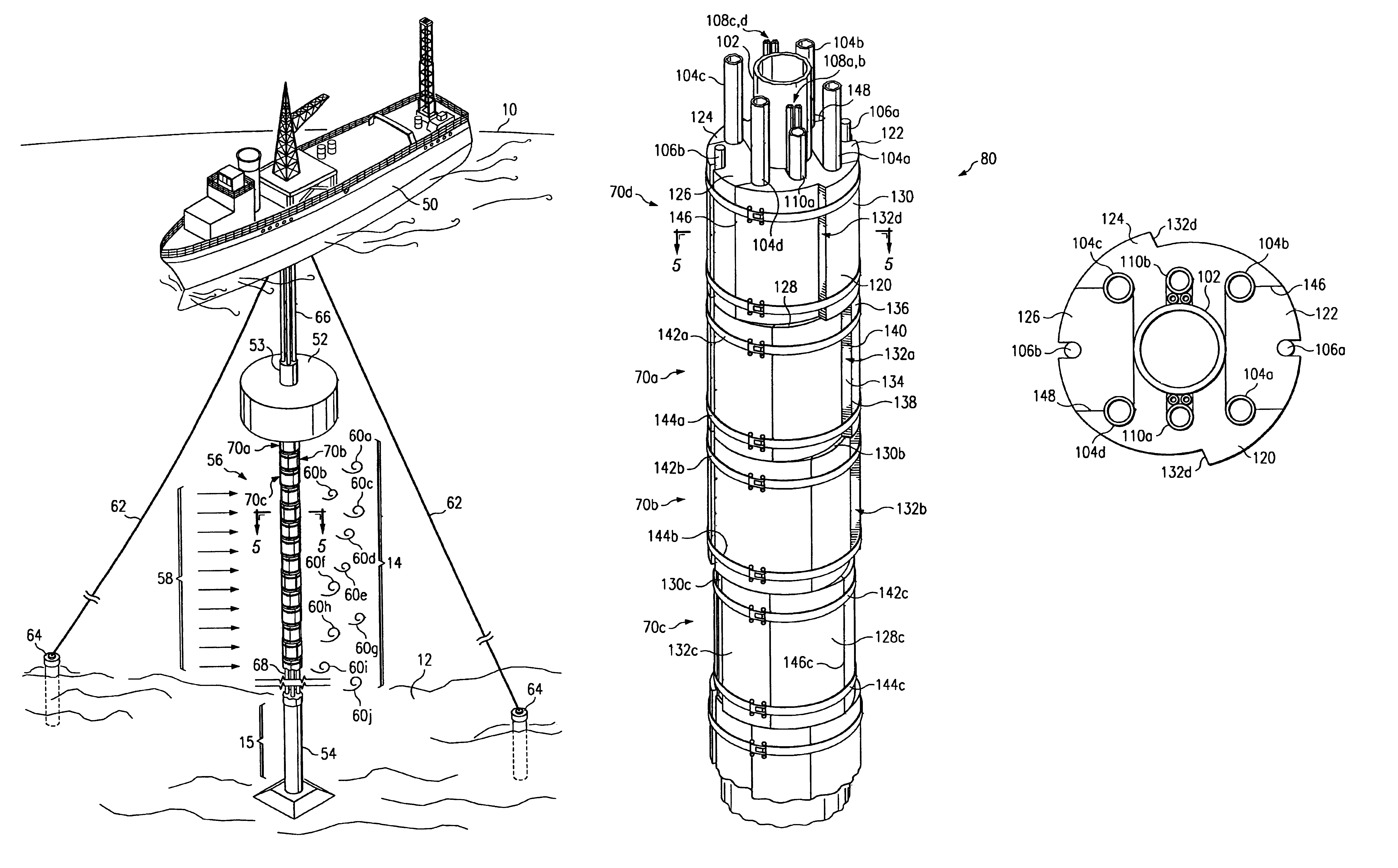
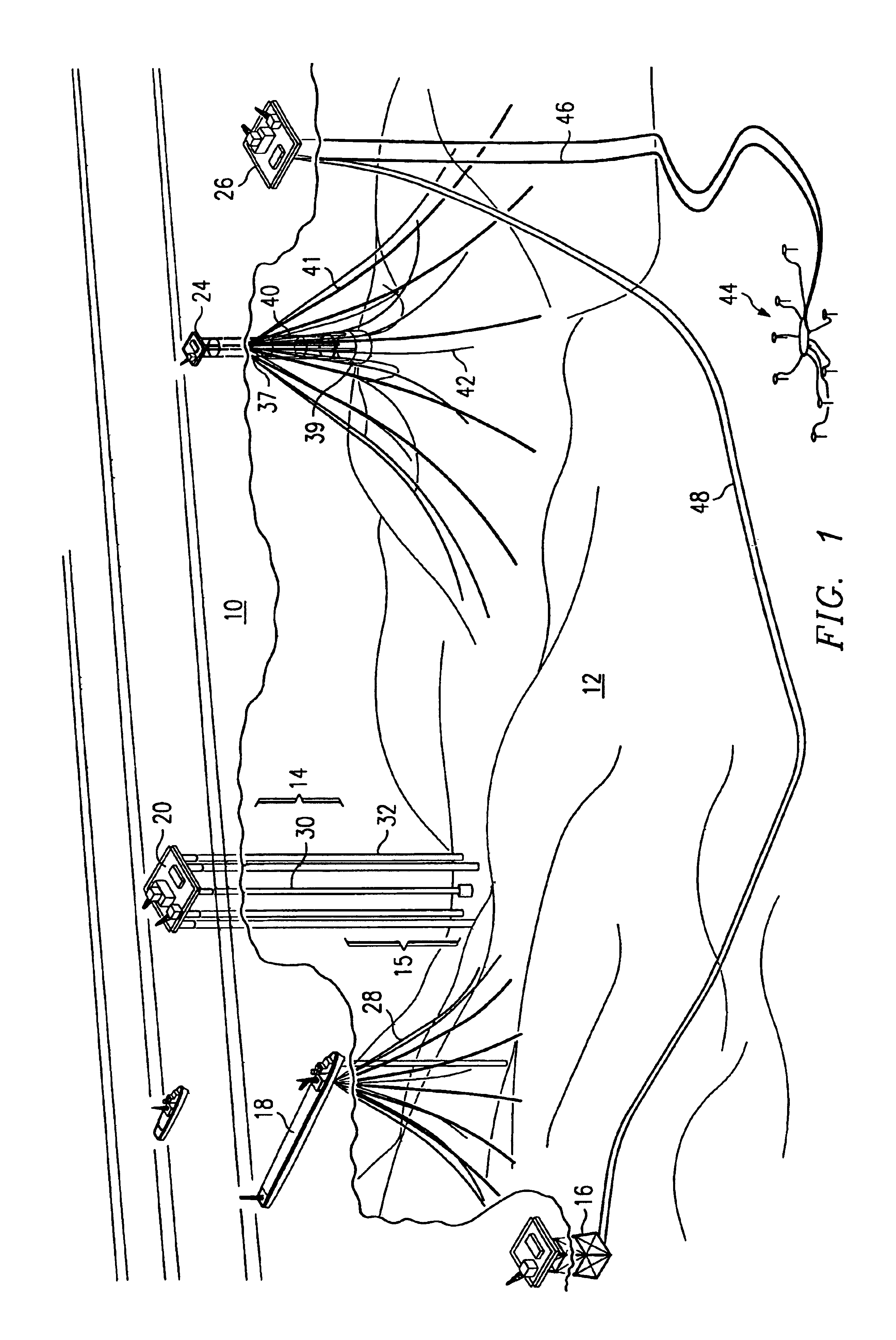
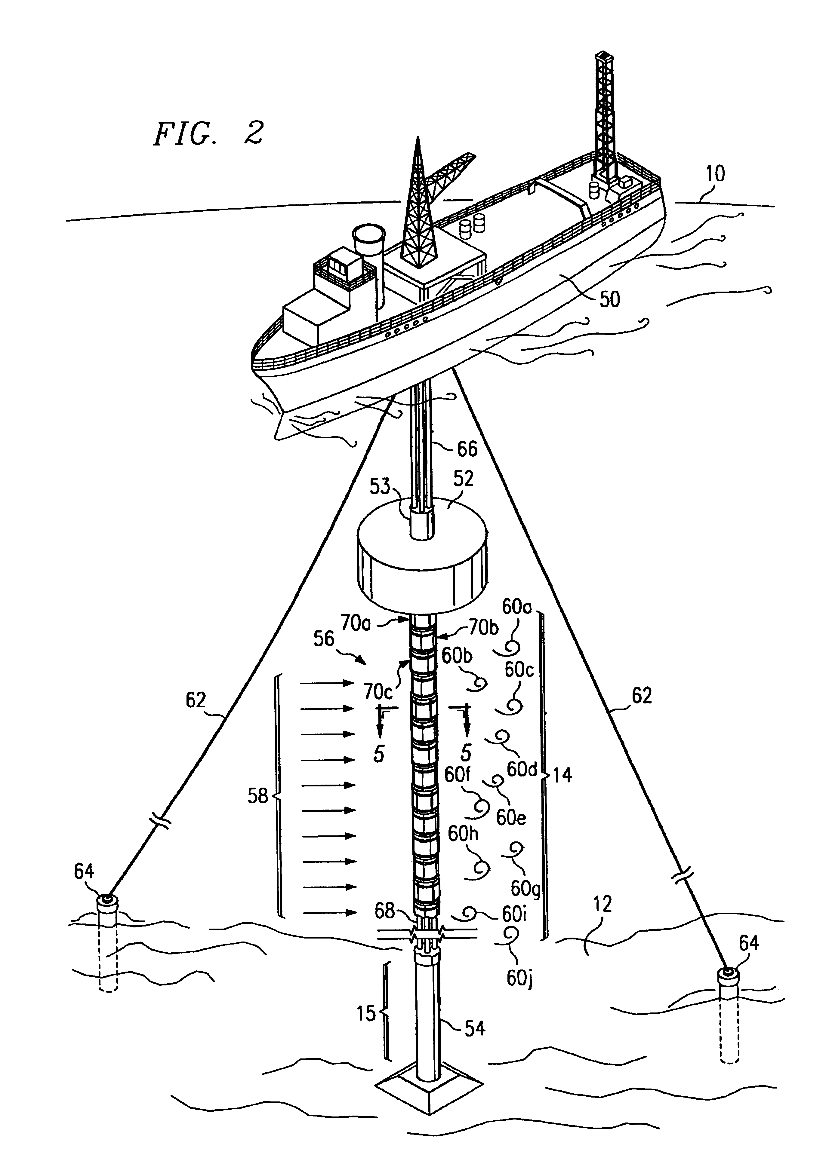
[0039]Referring to FIG. 1, which is a schematic depiction of floating production systems on the sea surface 10 and extending from the seabed 12 through a distance of ocean, including a portion 14 having sea currents and a portion 15 without significant sea currents. Examples of various ocean equipment to which the invention may be usefully applied are depicted, including a sea floor drilling rig 16, a ship 18, a columnar-supported drilling platform 20, and a spar platform 24, as well as a collection vessel 26. Risers 28 are shown extending from the sea...


PUM


Abstract

A mechanism to be applied to an exterior surface of a cylindrical structure for the reduction of the effect of Vortex Induced Vibration (VIV) in the cylindrical structure when immersed in flowing fluid, wherein the mechanism includes a generally cylindrical column having a central axis, an interior surface corresponding in size and shape to the exterior surface of the cylindrical structure to which the mechanism is to be applied and an outer surface defining a wall thickness. A reduced wall thickness is formed into the outer surface in a pattern to produce a discontinuity that interrupts the lengthwise coherence of vortex shedding of moving fluid from the outer surface when the cylindrical column is attached to the exterior of the cylindrical structure in the flowing fluid. The effect of VIV on the cylindrical structure is effectively reduced. The result is a submergible cylindrical assembly for positioning in a flowing body of water and having enhanced resistance to VIV.

Description

TECHNICAL FIELD OF THE INVENTION[0001]This invention relates in general to the field of solid and hollow cylinders, such as risers, hoses, pilings and pipes immersed in a fluid subject to relative motion between the cylinder and the fluid. In particular, the invention relates to a device and mechanism and method for reducing vortex-induced vibration caused by relative movement of water past a cylinder and also to a cylindrical assembly incorporating the inventive mechanism.BACKGROUND OF THE INVENTION[0002]Without limiting the scope of the invention, its background will be described primarily with reference to offshore risers used in sub-sea production wells as an example. Submerged cylindrically-shaped objects, such as risers, spars, or other elongated cylindrical structures used for under-sea oil or gas production, pumping, or loading are often exposed to relative movement of a body of fluid, particularly moving sea currents. Such elongated cylindrical structures are common in offs...

Claims


Application Information

Patent Timeline
Patent Type & Authority Patents(United States)
IPC IPC(8): E21B17/00E21B17/01
CPCE21B17/01F16L1/123
Inventor XU, QIQI, TAOMEASAMER, JEFFERY C.
Owner TECH FRANCE SA
Why Eureka
Try Eureka