[0008]The present invention aims at eliminating the drawbacks found in the above-cited conventional structures. Accordingly, it is an object of the invention to provide a multi-axial machine tool which not only can facilitate the adjustment of the mounting precision of the turning table, the maintenance of the adjusted mounting precision and the removal of the turning table but also, in the
cutting operation, can prevent the
cut chips from accumulating in the interior of the machine tool.
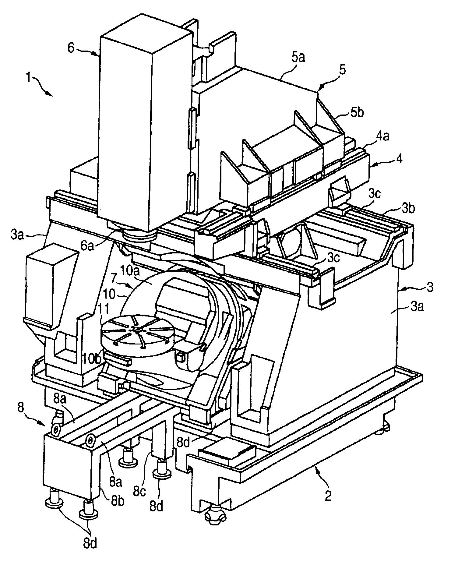
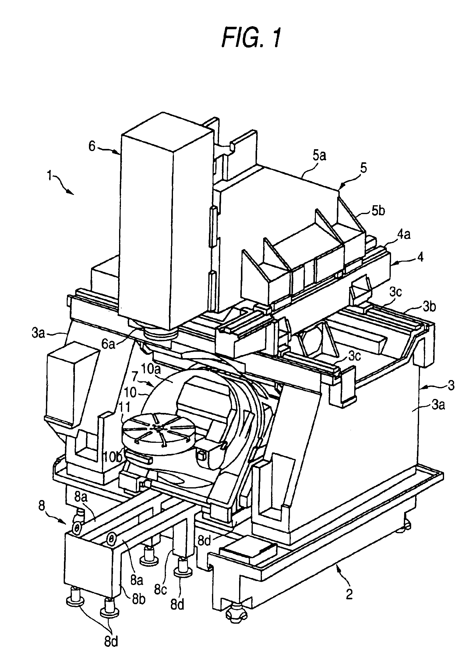
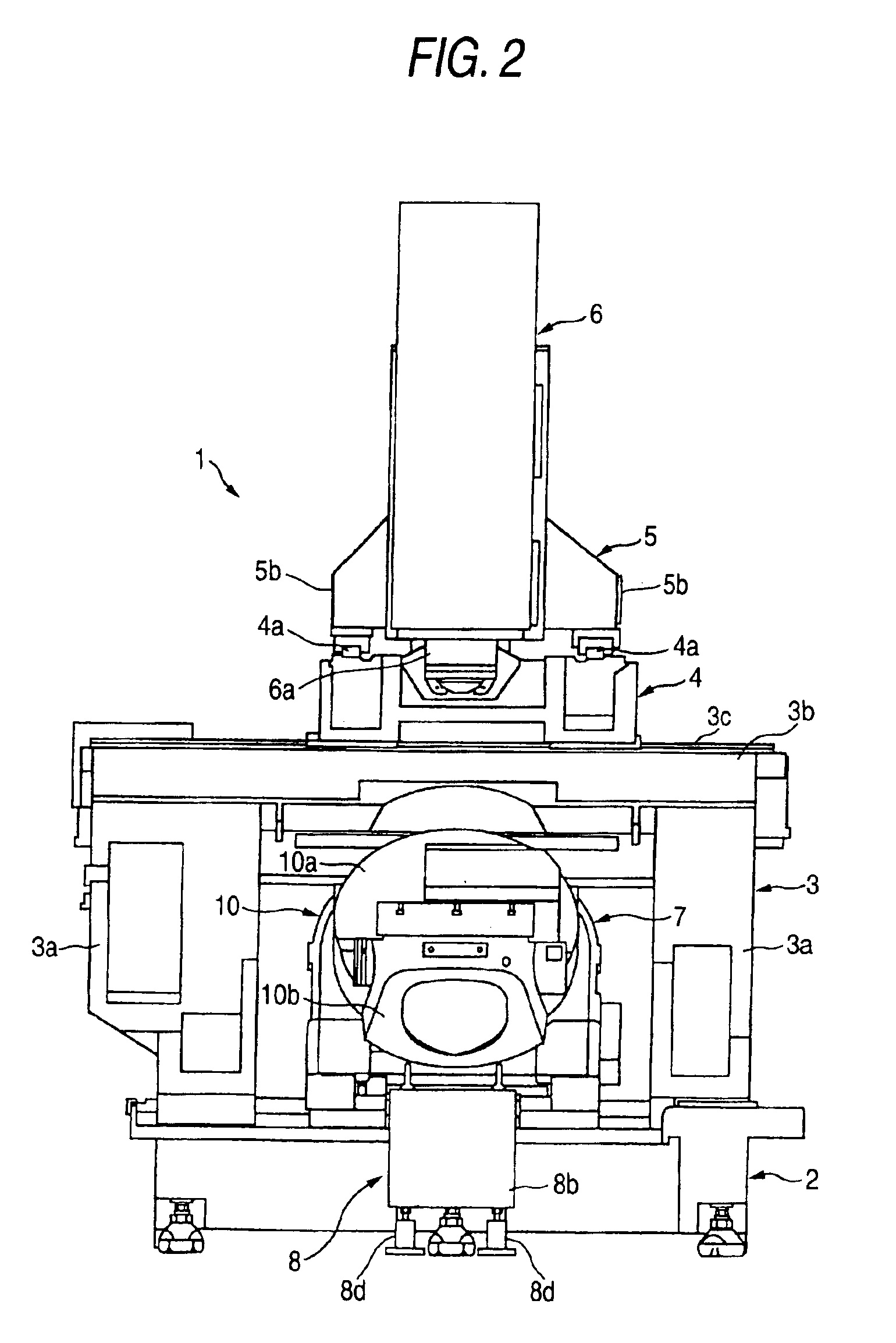
[0029]According to the invention, the table unit is structured not only such that the table base, the turning table turnably disposed on the inclined turning surface of the table base, and the work table placed on the table support portion of the turning table are assembled together into a unit body, but also such that it can be mounted onto and detached from the upper surface of the leg. Thanks to this, the table base and turning table can be assembled outside the machine tool, the assembling precision thereof can be enhanced, and the thus-enhanced assembling precision can be maintained easily and positively. Also, when the table unit requires maintenance, the table unit can be detached externally of the machine tool for maintenance, thereby being able to facilitate the maintenance operation of the table unit.
[0031]According to the invention, because the clearance between the inclined turning surface of the table base and portal
bed is covered with the cover member, it is possible to prevent
cut chips from piling up between the table unit and portal bed, thereby being able to reduce the number of man-hours necessary for the
cut powers discharging operation.
[0033]According to the invention, because the table unit mounting and detaching jig comprises the support member to be inserted from the front surface side of the machine tool into between the leg upper surface and the bottom surface of the table unit and the lift mechanism for raising and lowering the support member, for detaching the table unit, after the fixing of the table unit to the leg upper surface is released, the inserted support member may be raised up to thereby move the table unit onto the support member and the table unit may be then slided externally of the portal bed, so that the table unit can be detached from the leg upper surface easily and positively.
[0034]Also, for mounting the table unit onto the leg, the table unit may be placed onto the support member held at its raised position and may be then moved and fixed to its mounting position; and, after then, the support member may be lowered to thereby move the table unit onto the placement surface of the leg and may be then fixed to the leg place surface. That is, the table unit can be fixed onto the upper surface of the leg easily and positively.

