Golf club head

a golf club and head technology, applied in the field of golf club head, can solve the problems of affecting the increase of carry, the insufficient effect of increasing the initial velocity of the ball, and the small deformation of the face surface, so as to achieve the effect of easy manufacturing and increase of carry

Active Publication Date: 2005-09-27
BRIDGESTONE SPORTS
View PDF15 Cites 91 Cited by
  • Summary
  • Abstract
  • Description
  • Claims
  • Application Information

AI Technical Summary

Benefits of technology

[0009]It is an object of the invention to provide a golf club head easily manufactured while the carry can be increased due to increase in launch angle even when a golfer having a low head speed uses the golf club head.
[0011]In the golf club head configured as described above, the longitudinal elastic modulus of the crown portion is made smaller than that of any other member including the sole portion, to increase the launch angle of a ball at the time of impact. As a result, even when a golfer having a low head speed uses the golf head club, the launch angle is increased so that the carry can be increased. As a result even when a golfer having a low head speed uses the golf head club, the launch angle is increased so that the carry can be increased.
[0013]As a result, the vicinity of the uppermost edge of the face portion of the top plate does not suffer hardening due to the welding. Thus, the crown portion and the vicinity of the uppermost edge of the face portion, which are made from the thin top plate, are bent easily when a ball is hit. Accordingly, the golf club head has a high repulsive property so that the carry increases.
[0014]In addition, in the golf club head according to the invention, the region from the crown main portion to the upper edge of the face portion is formed out of an integrated top plate, while the face main portion is formed out of an integrated face plate. The top plate and the face plate can be produced separately. Thus, the face plate and the top place can be produced easily even when the face plate is made thicker than the top plate.

Problems solved by technology

However, when a golfer having a low head speed uses such a golf club head, the deformation of the face surface is so small that the effect of increasing the initial velocity of a ball is insufficient.
In addition, a low trajectory of the ball may hinder increase of the carry.
Such press working on members different in thickness requires a high degree of difficulty in working in view of working technology.

Method used


Image

  • Golf club head
  • Golf club head
  • Golf club head

Examples


Embodiment Construction

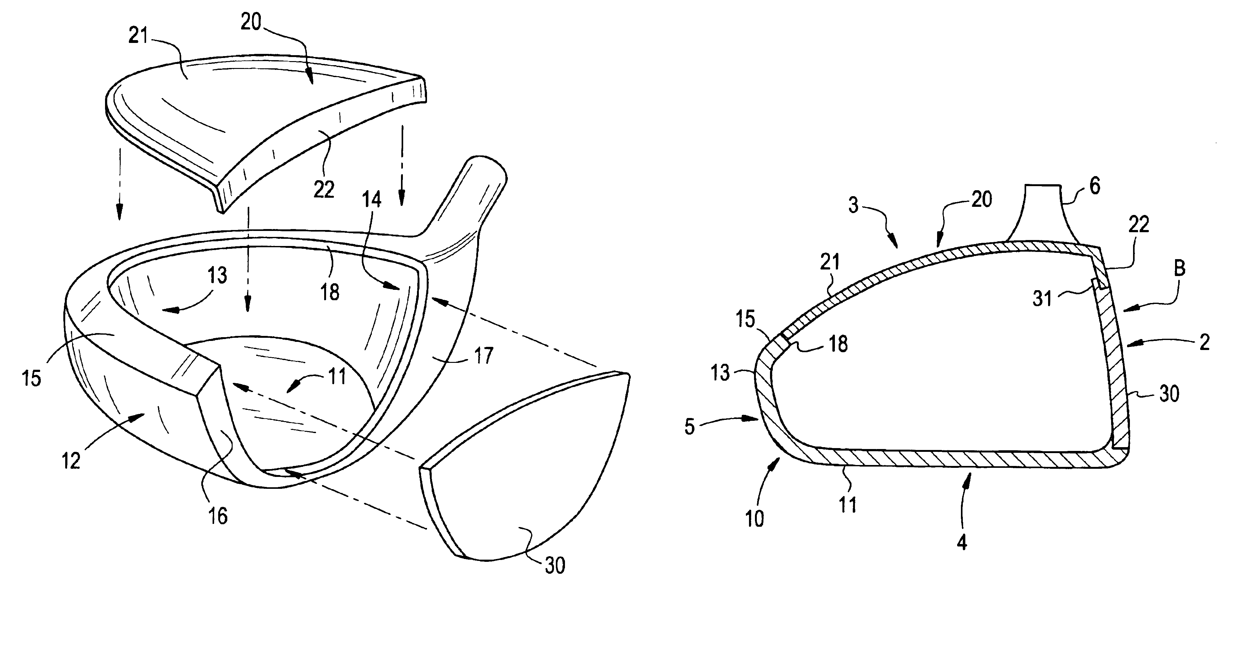
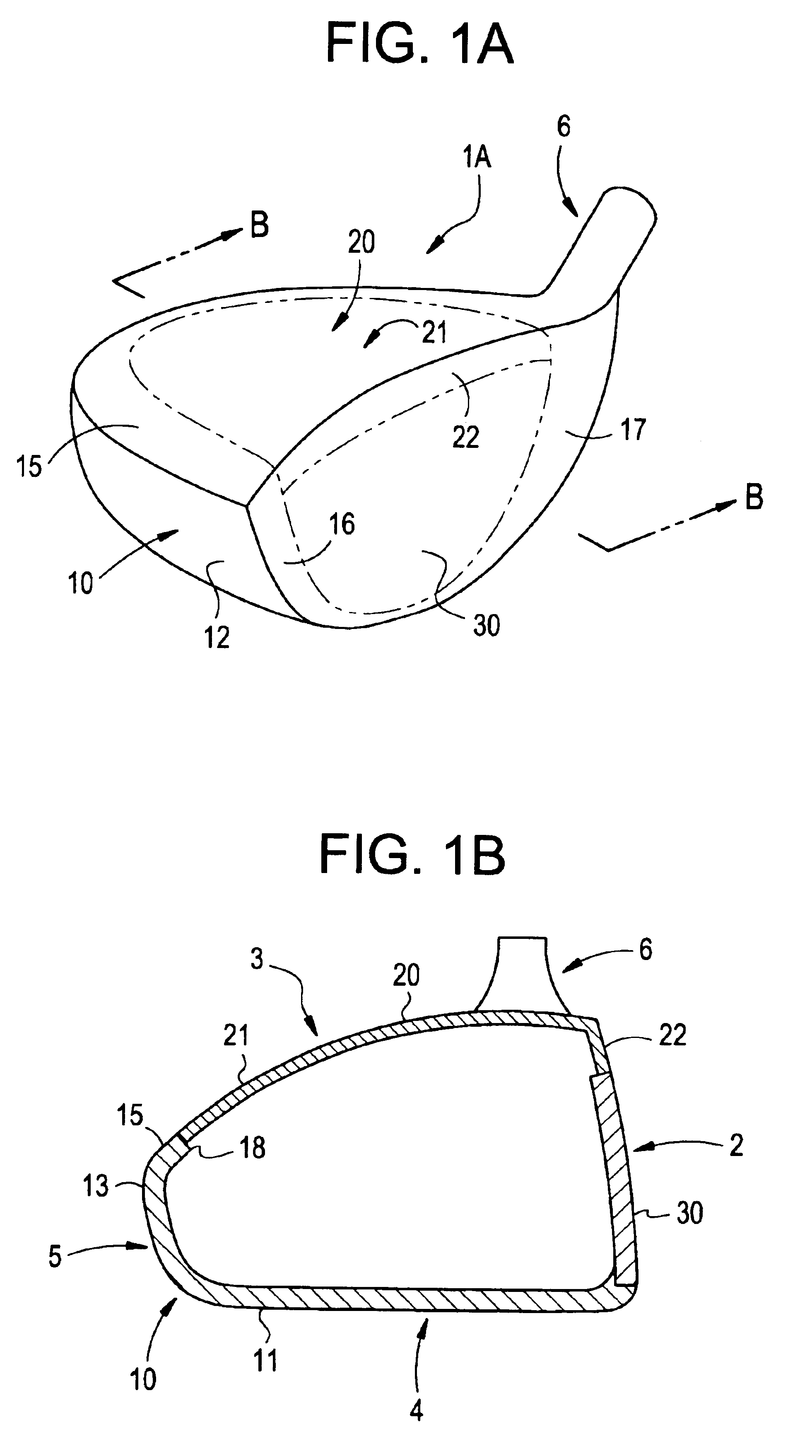
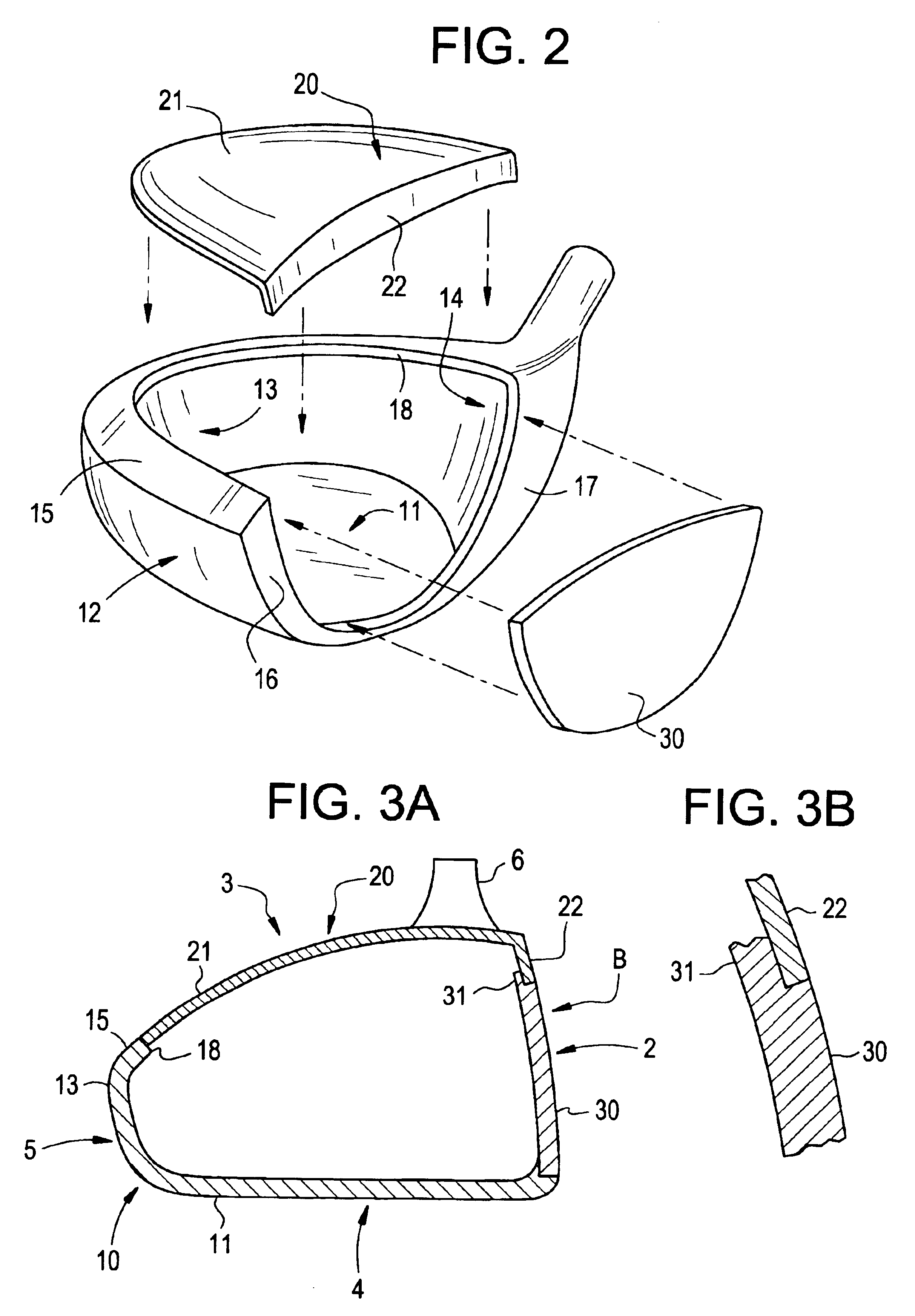
[0025]Embodiments of the invention will be described below with reference to the drawings. FIGS. 1(a) and 1(b) are a perspective view and a sectional view of a golf club head according to the embodiment. FIG. 2 is an exploded perspective view of the golf club head.

[0026]A golf club head 1A includes a face portion 2, a crown portion 3, a sole portion 4, a side portion 5 and a hosel portion 6. The golf club head 1A is formed out of a head body 10, a top plate 20 and a face plate 30 integrated by welding such as laser welding or plasma welding. Incidentally, plasma welding or laser welding is high in energy density, and deep in melting-in in comparison with TIG welding. Thus, accurate and nice-looking welding can be expected.

[0027]As is shown clearly in FIG. 2, the head body 10 includes a bottom surface 11 forming the sole portion 4, a toe erected surface 12, a back erected surface 13, a heel erected surface 14, which form the side portion 5, a crown flange 15, which projects from uppe...


PUM


Abstract

A metal hollow golf club head includes a head main body, a top plate, and a face plate. The head main body includes both side edges and a rear edge of the crown portion, both side edges of a face portion, and a side portion formed integrally therewith. The top plate includes a crown main portion, which is a member of the crown portion other than the both side edges and rear edge of the crown portion, and an upper edge of the face portion integrally. The face plate includes a face main portion, which is a member of the face portion other than the both side edges and upper edge of the face portion. The head main body, the top plate, and the face plate are coupled. A metal material of the top plate has a longitudinal elastic modulus lower than the metal materials of the head main body and face plate.

Description

BACKGROUND OF THE INVENTION[0001]1. Field of the Invention[0002]The present invention relates to a hollow golf club head made from metal, and particularly relates to a golf club head having a wood type shape or another shape close to the wood type shape.[0003]2. Description of the Related Art[0004]Hollow golf club heads made from metal are used broadly as wood type golf club heads such as drivers or fairway woods. Generally, as shown in FIG. 4, a wood type hollow golf club head 1 includes a face portion 2 for hitting a ball therewith, a crown portion 3 forming the top portion of the golf club head, a sole portion 4 forming the bottom portion of the golf club head, a side portion 5 forming the side portion on the toe side, back side and heel side of the golf club head, and a hosel portion 6. A shaft 7 is inserted into the hosel portion 6 of the golf club head 1, and fixed thereto by an adhesive agent or the like. Incidentally, recently, many golf club heads called utility golf club h...

Claims


Application Information

Patent Timeline
Patent Type & Authority Patents(United States)
IPC IPC(8): A63B53/04A63B102/32
CPCA63B53/04A63B53/0466A63B2053/0408A63B2053/0437A63B2053/0416A63B2053/0412A63B53/0408A63B53/0412A63B53/0416A63B53/0437E05Y2600/622E06B1/18E06B1/347A63B60/00
Inventor IMAMOTO, YASUNORIMATSUNAGA, HIDEO
Owner BRIDGESTONE SPORTS
Why Eureka
Try Eureka