Rotary blood pump diagnostics and cardiac output controller

a blood pump and controller technology, applied in the field of pump controller and method of operation, can solve the problems of blood clots, lost sensor sensitivity, and sabotaging the reliability of sensors,

Inactive Publication Date: 2005-09-27
WORLD HEART
View PDF13 Cites 266 Cited by
  • Summary
  • Abstract
  • Description
  • Claims
  • Application Information

AI Technical Summary

Problems solved by technology

However this approach is saddled with reliability issues of sensors directly exposed to blood, in addition to wires and cable associated with such sensors.
Sensor placement directly in the blood flow is undesirable because the blood can cause malfunction of the sensor due to contamination of the sensing element and wiring, or due to blood clotting around the sensing element resulting in lost sensitivity of the sensor.
The sensor itself can also damage the blood cells themselves creating blood clots.
However, these sensors are difficult to implement within a patient, lack the required sensitivity, and are quite expensive.
For example, a speed set point of the heart pump that is set at a predetermined point compared to ventricular collapse may not be the optimum speed for a particular patient.
Additionally, incrementing the speed set point of a heart pump toward an imminent ventricular collapse comparison point may be dangerous.
Additionally, choosing the speed set point of a heart pump by arbitrarily setting the speed a predetermined amount away from a failure point does not provide any diagnostic feedback to the physician monitoring the patient.

Method used


Image

  • Rotary blood pump diagnostics and cardiac output controller
  • Rotary blood pump diagnostics and cardiac output controller
  • Rotary blood pump diagnostics and cardiac output controller

Examples


Embodiment Construction

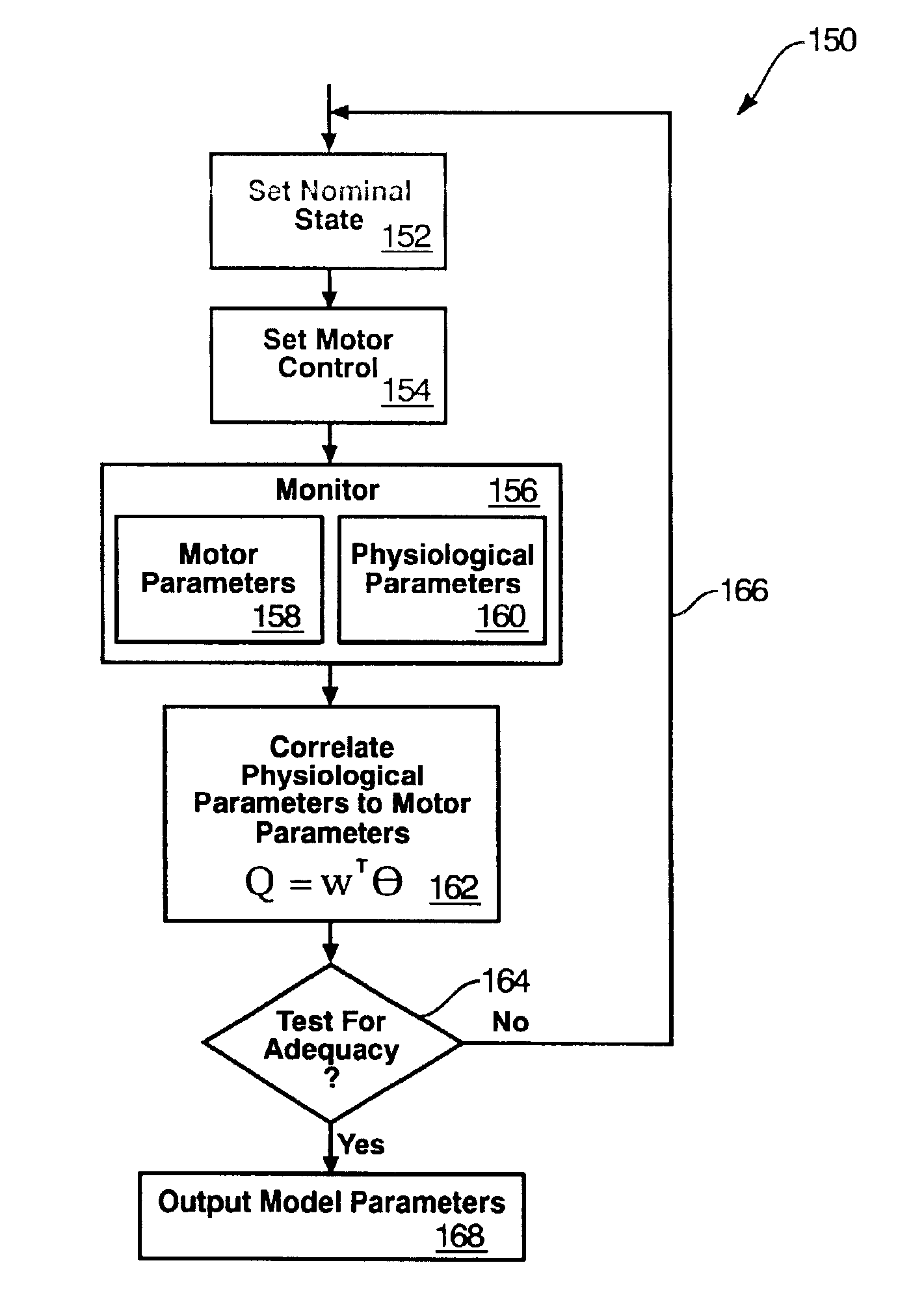
[0021]It will be readily understood that the components of the present invention, as generally described and illustrated in the Figures herein, could be arranged and designed in a wide variety of different configurations. Thus, the following more detailed description of the embodiments of the system and method of the present invention, as represented in FIGS. 1 through 10, is not intended to limit the scope of the invention, as claimed, but is merely representative of the presently preferred embodiments of the invention.

[0022]The presently preferred embodiments of the invention will be best understood by reference to the drawings, wherein like parts are designated by like numerals throughout.

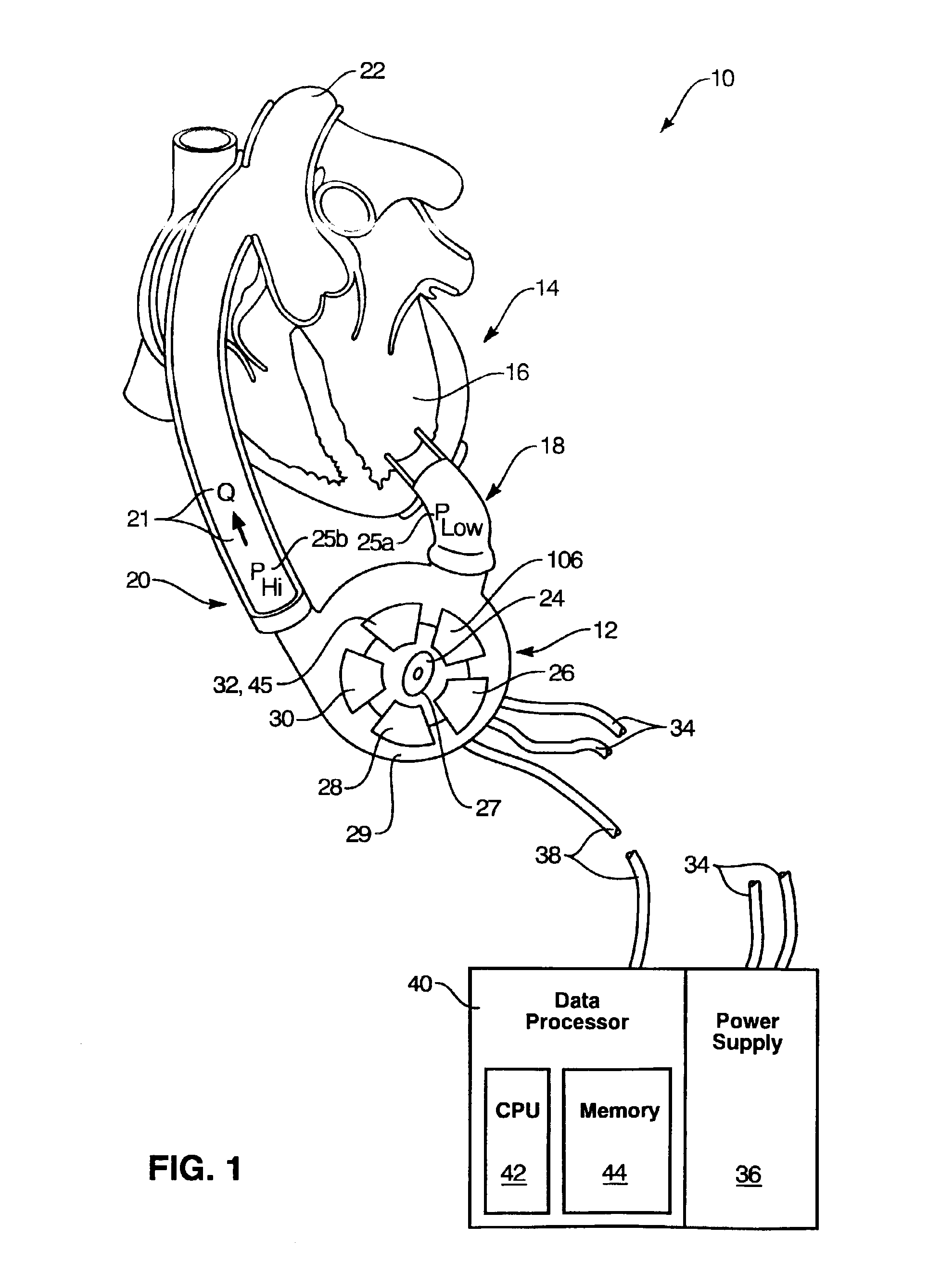
[0023]Referring to FIG. 1, a system 10 operates to provide an effective assistance to a failed ventricular portion of a heart. In general, such a system 10 may include a ventricular assist device 12 (VAD 12) operably connected to a native heart 14 of a patient. Typically, a native ventricle 16 h...


PUM


Abstract

A method and apparatus for controlling a ventricular assist device are disclosed. The method includes the step of providing a ventricular assist device which can be defined in terms of operational parameters such as pump speed or current. Measuring at least one physiological parameter reflecting a physiological state corresponding to a patient. Correlating at least one physiological parameter measured from the patient to at least one operational parameter using an estimation method. Selecting a physiological state definable by desired values of the physiological parameters. Monitoring at least one operational parameter. Controlling input values of the operational parameter based on output from the monitoring step. The apparatus includes a pump driven by a motive drive and having an impeller. A sensor detects the value of an operational parameter of the pump. A processor provides a statistical correlation between patients physiological parameter and the operational parameter of the pump and adjusts the operational parameter to affect a predetermined optimal physiological state.

Description

THE FIELD OF THE INVENTION[0001]This invention relates to a pump controller and method of operating same. More particularly, the invention relates to a rotary blood pump controller and method for real time control of the pump to give optimum performance to the patient benefitting from the pump and to give diagnostic feed back to those monitoring the patient.BACKGROUND[0002]The invention described here is related to the clinical use and automatic control of a blood pump in the human circulation system. In general there are various physiological parameters that are of interest to clinicians that care for patients that are undergoing circulatory assistance from a mechanical device. Many of these same parameters may be desirable to be obtained for use in an automatic cardiac output controller to be used in combination with the mechanical pump. Examples of physiological parameters that could be used include flow through the pump and pressures at the inflow and the outflow of the pump.[00...

Claims


Application Information

Patent Timeline
Patent Type & Authority Patents(United States)
IPC IPC(8): A61M1/10A61M1/12
CPCA61M1/101A61M1/12Y10S415/90A61M2205/3334A61M2205/33A61M2205/3303F04D15/0088A61M60/148A61M60/88A61M60/216A61M60/178A61M60/523A61M60/538A61M60/531A61M60/515
Inventor BEARNSON, GILLJACOBS, GORDON B.
Owner WORLD HEART
Why Eureka
Try Eureka