
Antenna array for moving vehicles

a technology for moving vehicles and antennas, applied in the field of antennas, can solve the problems of antennas protruding significantly, difficult for a typical antenna to track a signal source, and adversely affecting the aesthetics of the vehicl

Inactive Publication Date: 2005-09-27
EMS TECHNOLOGIES
View PDF20 Cites 34 Cited by
  • Summary
  • Abstract
  • Description
  • Claims
  • Application Information

AI Technical Summary

Benefits of technology

[0010]Briefly described, in a first preferred form the present invention comprises a low-profile antenna for mounting to a vehicle. The low-profile antenna includes an array of antenna elements for receiving incoming electromagnetic signals. An azimuth drive is provided for physically rotating the array of antenna elements about an azimuth axis. Furthermore, an altitude drive is provided for physically pivoting the individual antenna elements to change the elevation angle at which the individual antenna elements point. With this construction, the antenna system can be pointed at a source, such as a satellite, by operation of the azimuth drive and / or the altitude drive and can maintain the pointing over a wide range of vehicle orientations.
[0017]Advantageously, by utilizing an array of relatively small elements, the overall profile of the system can be kept low. At the same time, the individual elements are controlled to maintain good pointing at the source. Collectively, the output from the array of elements is adequate to deliver a good, usable signal even from a relatively weak input signal, such as from a direct broadcast satellite. The invention therefore provides a low profile antenna system which is effective for receiving a variety of signals and is well-suited for use with moving vehicles. The low profile nature of the antenna system makes it practical to use the system on a wide variety of vehicles. Such vehicles would include automobiles, vans, trucks, buses, trains, boats, airplanes, tractors, off-road vehicles, etc.
[0018]One exemplary application for the invention is the use of the antenna on moving vehicles to receive DBS television and audio signals from a geosynchronous (fixed orbit) satellite. In such an application, it should be noted that a single satellite typically broadcasts its signal over a very wide area, such as North America, with the result being that the signal to be picked up at the vehicle is rather weak. This would ordinarily indicate the use of a somewhat large antenna. The present invention allows the rather weak signal to be picked up using the array of elements and combined into a signal of sufficient strength to be useful. The present invention also allows the antenna to be trained on and track the satellite, despite movement of the vehicle in various orientations. Also, the invention accomplishes this while maintaining a rather low, unobtrusive profile that does not interfere excessively with the airflow past the vehicle as the vehicle moves.

Problems solved by technology

Unfortunately, the movement of a vehicle makes it difficult for a typical antenna to track a signal source.
The antenna could be made to track side-to-side (azimuth) and up and down (elevation), but if the antenna is of substantial size, this has disadvantages.
One such serious disadvantage is that the antenna might then protrude significantly at times, interfering with the smooth airflow over the vehicle or adversely affecting the aesthetics of the vehicle.
Unfortunately, the electronic hardware typically needed for such scanning by applying varying phase shifts is rather expensive, limiting the practical application of such antenna arrays to military or similar applications.
While such dish antenna designs are useful for receiving the DBS signal at a building, these antennas are especially ill-suited for use on a moving vehicle.
This is so because this type of dish antenna presents a rather large profile, which can interrupt smooth airflow as the vehicle travels.
Indeed, the dish antenna is large enough and has a large enough profile that wind resistance and noise generated thereby would be very objectionable if one were to mount the dish antenna to the outside of the vehicle.
Moreover, because of the large profile of the dish antenna, mounting this antenna securely enough to maintain a stable position despite wind resistance presents a formidable challenge.
As mentioned above, mounting a dish antenna to a vehicle presents an additional challenge in the difficulty of keeping the antenna trained on the satellite.
The reason for the difficulty is that the vehicle changes orientation in use.
In general, this is impractical.

Method used


Image

  • Antenna array for moving vehicles
  • Antenna array for moving vehicles
  • Antenna array for moving vehicles

Examples


Embodiment Construction

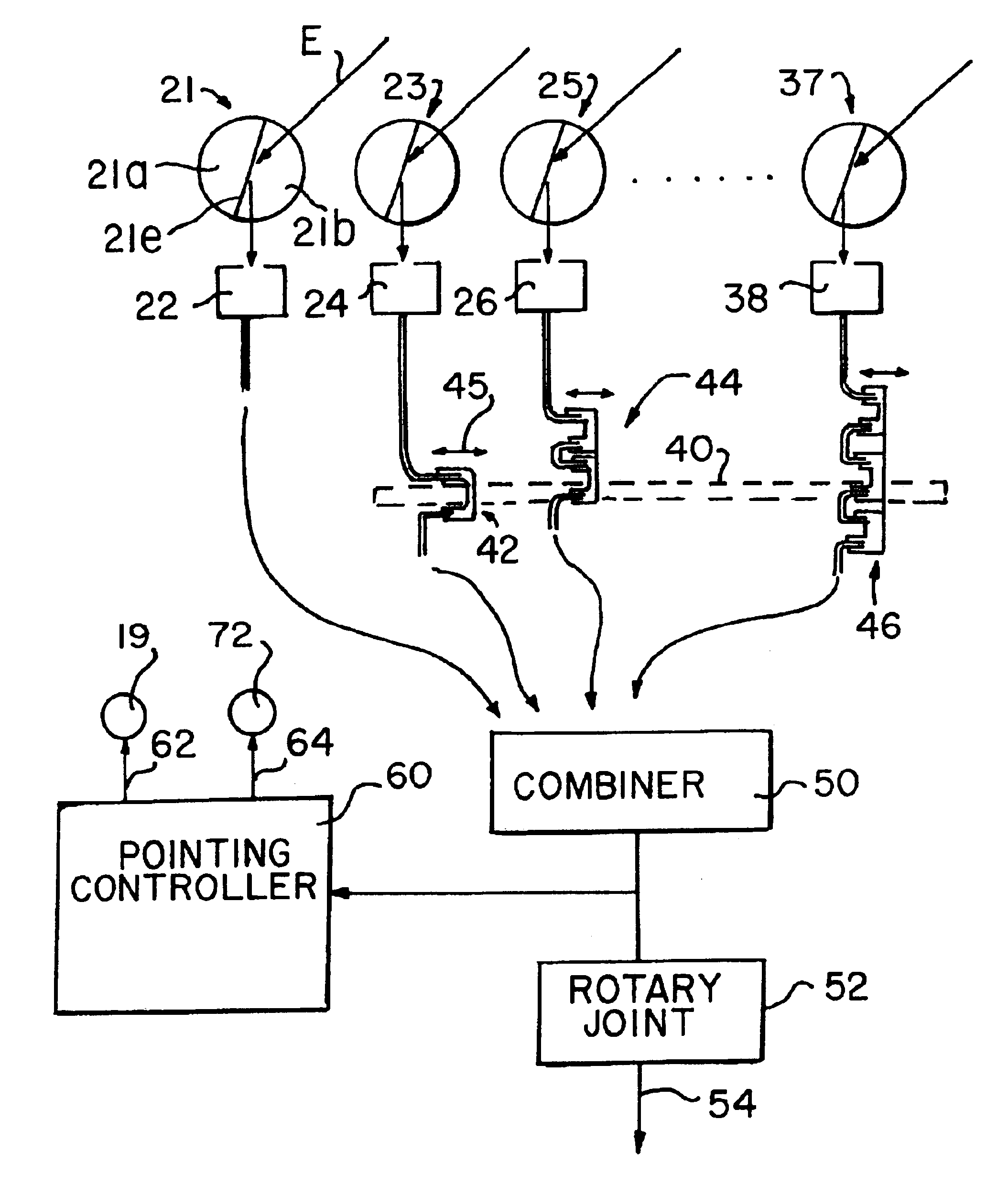
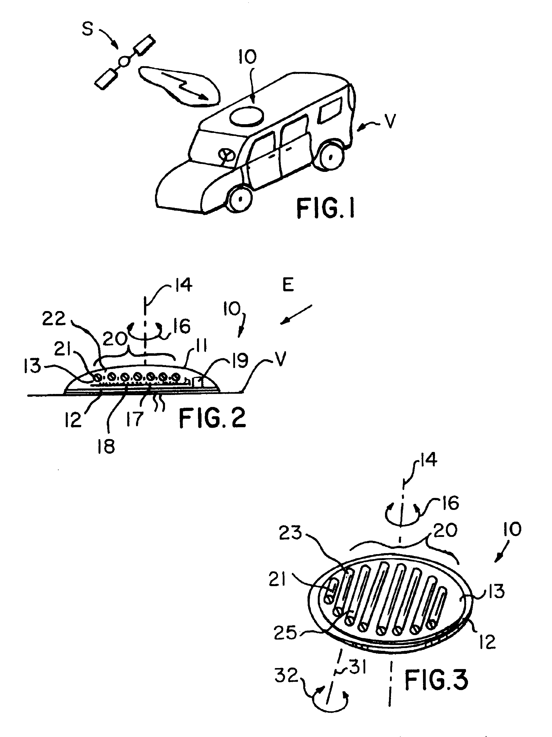
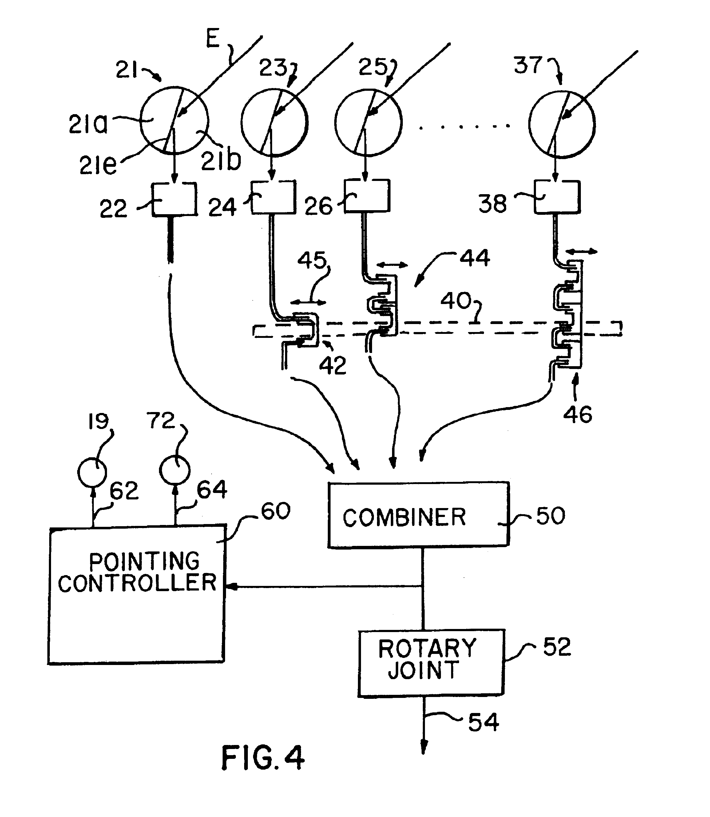
[0031]Referring now in detail to the drawing figures, in which like reference numerals refer to like parts throughout the several views, FIG. 1 is a schematic illustration of an antenna system 10 according to a preferred form of the invention and shows the antenna system 10 mounted to a van V for receiving signals while the van moves, such as from a DBS satellite S. The antenna system 10 has a rather low profile, making it especially useful for mounting to the surface of a vehicle. In particular, the height of the system is much smaller than its transverse dimension (diameter, if the antenna system is round). For example, it is contemplated that if implemented as a receive antenna for receiving DBS signals, the antenna system typically would have a round overall shape, with a diameter of about 24 to 36 inches and would have a height of only about 2 to 4 inches. Of course, those skilled in the art will recognize that while the exemplary embodiments of the invention shown in the figur...


PUM


Abstract

A low-profile antenna system to be mounted to a moving vehicle for receiving signals, such as from a Digital Broadcast Satellite, includes a base for mounting to the surface of the vehicle, a platen mounted to the base for rotation, an azimuth drive motor for rotating the platen, an array of half-cylinder antenna elements mounted to the platen, an elevation drive motor for pivoting the antenna elements individually about their axes to change the elevation at which the antenna elements are pointing, and a cover. The azimuth drive motor and the elevation drive motor together allow the array of antenna elements to be pointed at a satellite over a wide range of vehicle orientations.

Description

CROSS-REFERENCE TO RELATED APPLICATIONS[0001]The present application claims the priority benefit of U.S. provisional patent application Ser. No. 60 / 345,065, filed on Nov. 9, 2001 and incorporates the same herein by reference.TECHNICAL FIELD[0002]The present invention is directed generally to antennas and particularly to antenna systems for mounting to a vehicle for receiving signals, such as from a Direct Broadcast Satellite (DBS).BACKGROUND OF THE INVENTION[0003]With the proliferation of various communication and entertainment technologies, it is becoming increasingly desirable to receive signals in moving vehicles. Today's vehicles sometimes receive radio, wireless telephone signals, email, electronic data, Global Positioning Satellite (GPS) data, television signals, etc. This need for in-vehicle reception exists in consumer automobiles, commercial automobiles and trucks, commercial and private airplanes, pleasure and commercial boats, and in military vehicles of all sorts, just t...

Claims


Application Information

Patent Timeline
IPC IPC(8): H01Q3/20H01Q19/06H01Q19/10H01Q3/04H01Q3/02H01Q19/00H01Q3/26H01Q1/32H01Q21/00H01Q3/00H01Q3/08H01Q5/00H01Q21/08
CPCH01Q1/3275H01Q3/04H01Q3/08H01Q3/20H01Q3/26H01Q19/062H01Q19/104H01Q21/0043
Inventor HOWELL, JAMES M.FREEMAN, ROBERT A.
Owner EMS TECHNOLOGIES
Learn More