Device for changing channels in a digital television reception system

a technology of digital television and reception system, applied in the field of devices for changing channels in the digital television reception system, to achieve the effect of simple construction, rapid change of channels, and rapid “zapping

Inactive Publication Date: 2005-09-27
OMICRON CETI
View PDF8 Cites 12 Cited by
  • Summary
  • Abstract
  • Description
  • Claims
  • Application Information

AI Technical Summary

Benefits of technology

[0006]The aim of the present invention is, as it is in the known construction according to the partial description given above, primarily to make possible rapid change of channel in a digital TV reception system. Thus it should be possible to carry out rapid “zapping” between different TV channels by means of, for example, a remote control device. Furthermore, the new arrangement is to have a simpler construction than known connection arrangements, so that no expensive investment costs are required for its accomplishment.

Problems solved by technology

However, it is generally known for one skilled in the art that a certain time delay will arise in association with changing between different TV channels in such digital TV reception systems, and this can, in certain cases, can be experienced as a not inconsiderable source of irritation.

Method used


Image

  • Device for changing channels in a digital television reception system
  • Device for changing channels in a digital television reception system
  • Device for changing channels in a digital television reception system

Examples


Embodiment Construction

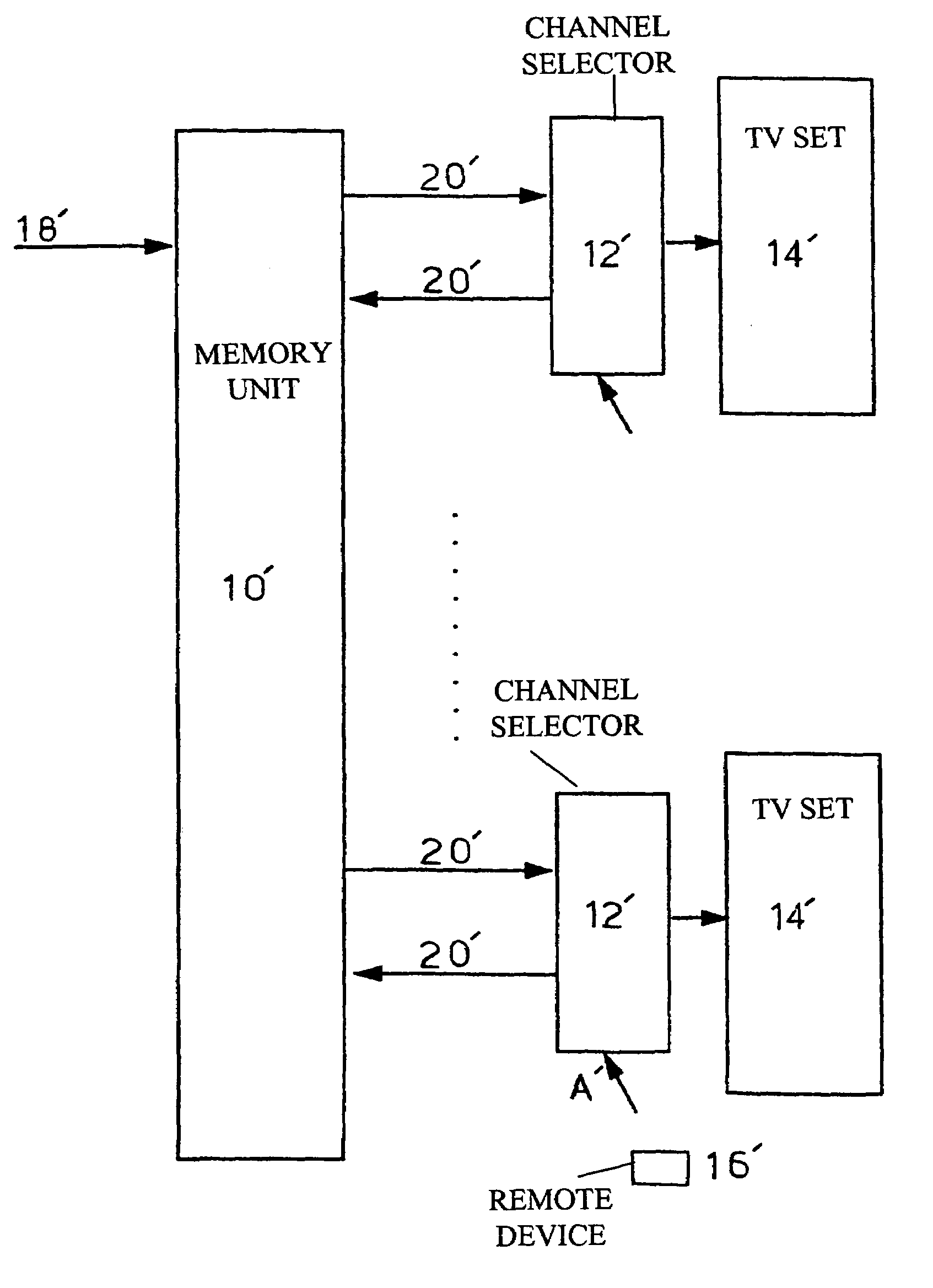
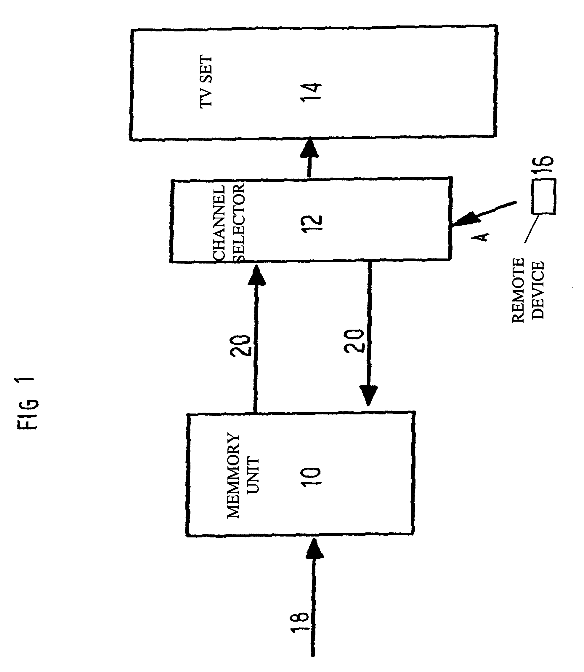
[0013]The example embodiment that is shown in FIG. 1 refers to a TV reception system whose main components consist of a memory unit 10, a channel selector 12, a TV set 14 and a remote control device 16. However, it should be clearly pointed out here that it is naturally possible to exploit the invention also in association with any other type of image display unit, for example, a computer; and that the remote control unit concerns only a special control device for the desired choice of channel.

[0014]An incoming TV communication link 18 is suggested at the far left of FIG. 1 that transfers all of the TV channels that can be displayed on the screen (not shown) of the TV set 14. The TV channels coming in over the communication link 18 are encoded in digital form in a known manner. In the memory unit 10 built up according to the principles of the invention, continuous storage occurs of a short sequence of a large number of incoming TV channels. It should, however, be noted that it is on...


PUM


Abstract

A device for changing channels in a digital TV reception system including an image display unit is presented. A communication link is connected to a memory unit that has two-way coupling with the channel selector of the image display unit. The memory unit is arranged to continuously store in the respective shift register of the memory unit a sequence of information, corresponding to at least one complete digital basic image and modifications between it and a next basic image, from several TV channels. A basic image pointer is associated with each shift unit of the memory unit, the basic image pointer continuously specifying a position of the basic image in the shift register associated with each shift unit, such that the selected TV channel after decompression is accessible for display on the screen by means of a control unit through the channel selector and the memory unit.

Description

CROSS-REFERENCE TO RELATED APPLICATIONSBACKGROUND OF THE INVENTION[0001]1. Field of the Invention[0002]The present invention concerns a device for changing channels in a digital television reception system with at least one image display unit in the form of a television set or equivalent for the reception of several television channels over an incoming communication link and display of the desired TV channel on the screen of the image display unit.[0003]2. Description of the Related Art[0004]It is well known that traditional, analogue TV reception systems will in the future gradually be replaced by digital TV reception systems. Further, certain interface units will become superfluous, which will lead to shorter signal processing times and in this way, also shorter transfer times. The new digital TV reception systems have the additional advantage that both image and sound quality are improved. However, it is generally known for one skilled in the art that a certain time delay will ar...

Claims


Application Information

Patent Timeline
Patent Type & Authority Patents(United States)
IPC IPC(8): H04N5/50H04N5/44H04N5/907
CPCH04N5/4401H04N5/50H04N21/4384H04N21/426H04N7/015
Inventor WRIFE, KENNETH
Owner OMICRON CETI
Why Eureka
Try Eureka