Process for producing electrophoretic display device

a production process and electrophoretic technology, applied in the direction of electrographic process equipment, instruments, optics, etc., can solve the problems of lowering display quality in some cases, and achieve the effect of suppressing the lowering of display quality

Inactive Publication Date: 2005-09-27
CANON KK
View PDF2 Cites 20 Cited by
  • Summary
  • Abstract
  • Description
  • Claims
  • Application Information

AI Technical Summary

Benefits of technology

[0011]An object of the present invention is to provide a production process of an electrophoretic display device which prevents a lowering in display quality.
[0017]According to the production process of the present invention, the second area contacts the insulating liquid in a cured state, so that it is possible to prevent the electrophoretic particles in the insulating liquid from being adsorbed by the second substrate. As a result, it becomes possible to suppress a lowering in display quality caused by the particle adsorption.

Problems solved by technology

As a result, a display quality has been lowered in some cases.

Method used


Image

  • Process for producing electrophoretic display device
  • Process for producing electrophoretic display device
  • Process for producing electrophoretic display device

Examples


example 1

[0045]An electrophoretic display device shown in FIG. 3 was produced and driven.

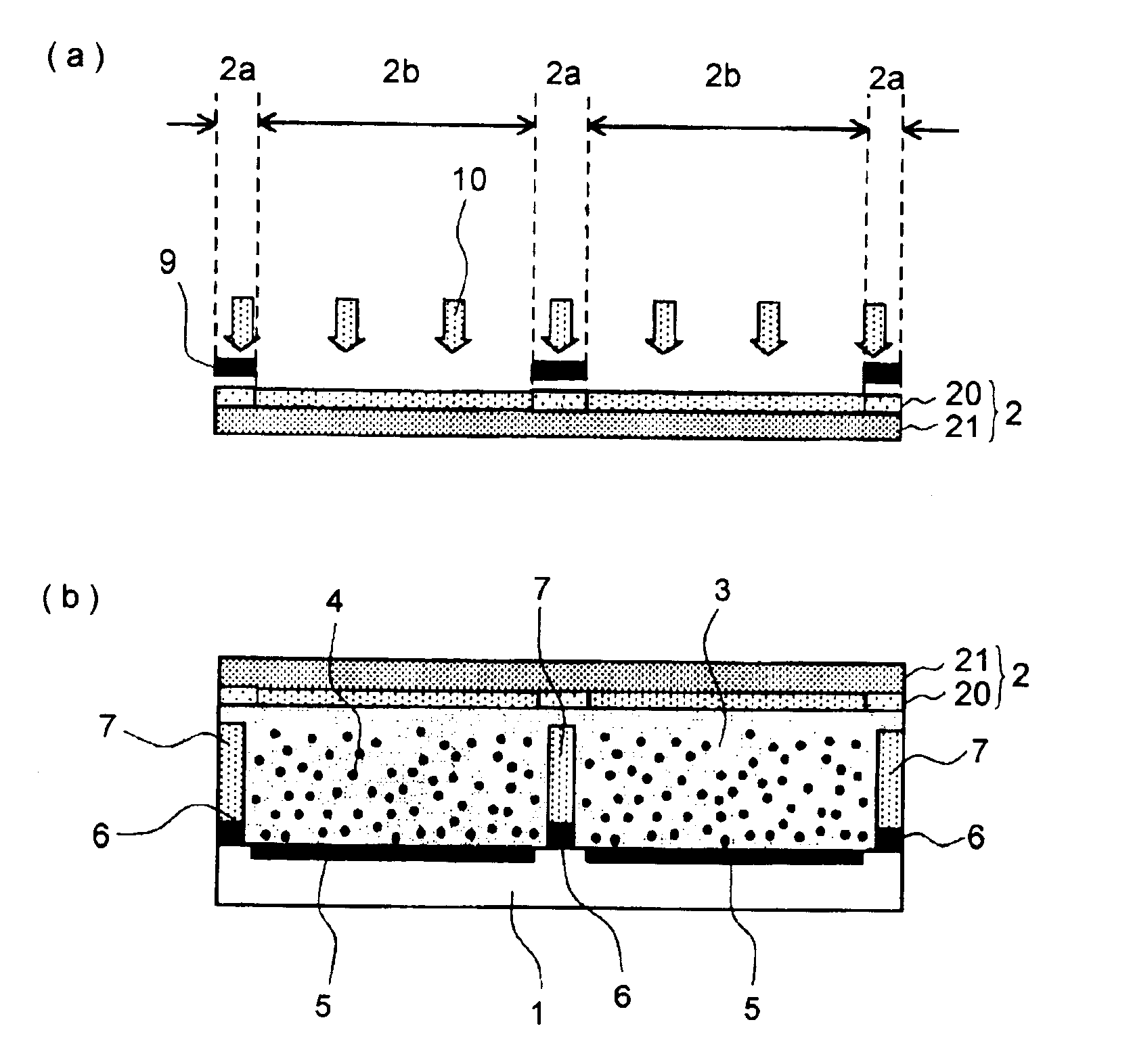
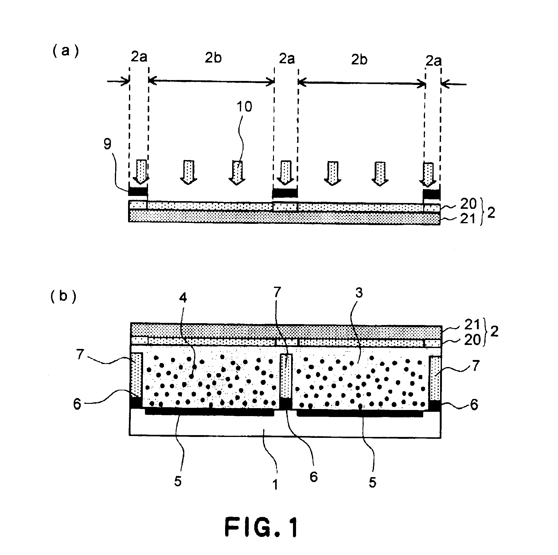
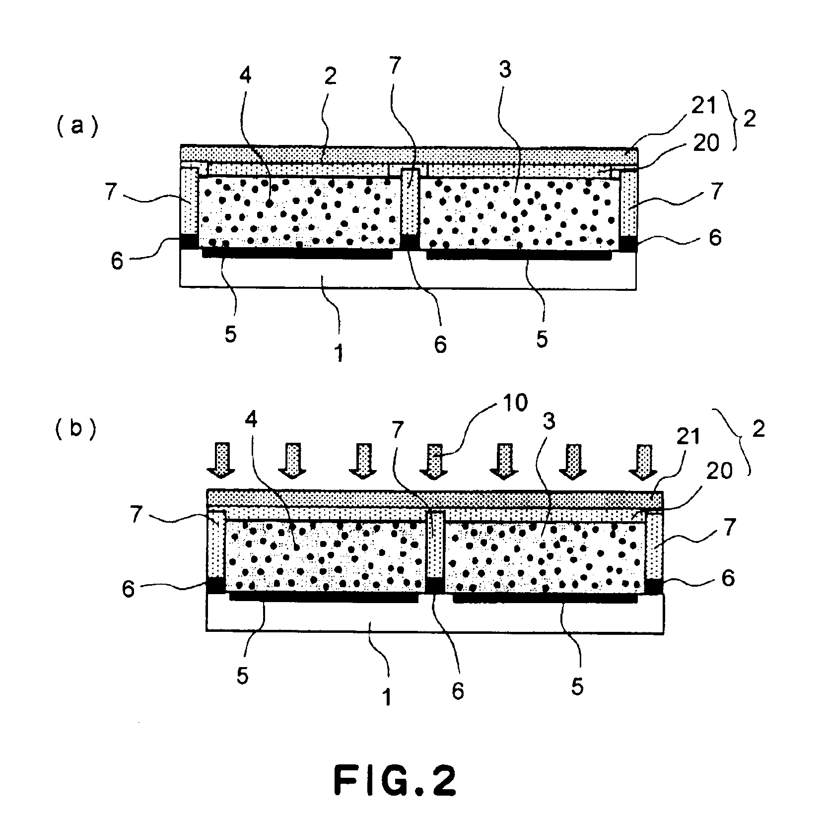
[0046]The electrophoretic display device had 200×200 pixels each having a size of 100 μm×100 μm. A 1.1 mm-thick glass plate was used as a first substrate 1, and a partition member 7 was disposed at a boundary of each pixel. The partition member 7 had a width of 5 μm and a height of 18 μm. A first electrode 5 was disposed at a central portion of each pixel so as to have a width of 80 μm and a height of 0.1 μm. A second electrode 6 was disposed at a pixel boundary between the partition member 7 and the first substrate 1 so as to have a width of 5 μm and a height of 0.1 μm.

[0047]The electrophoretic display device was produced in the following manner.

[0048]On the first substrate 1, an aluminum film was formed and patterned through photolithography and wet etching to form the first electrode 5. On the surface of the first electrode 5, an acrylic resin layer containing titanium oxide (not shown) was formed.

[00...


PUM

PropertyMeasurementUnit
particle sizeaaaaaaaaaa
sizeaaaaaaaaaa
heightaaaaaaaaaa

Abstract

An electrophoretic display device including first and second substrates disposed with a predetermined spacing, a partition member disposed between the first and second substrates, a plurality of electrophoretic particles and an insulating liquid which are sealed up by the substrates and the partition member, and first and second electrodes disposed close to the insulating liquid, is produced through a production process comprising the following steps (A), (B), (C) and (D): (A) a step of filling the insulating liquid and the electrophoretic particles in a recess defined by the first substrate and the partition member, (B) a step of placing a first area of the second substrate to be in contact with the partition member in an uncured state and a second area of the second substrate to be in contact with the insulating liquid in a cured state, (C) a step of causing the first area of the second substrate to contact the partition member and the second area of the second substrate to contact the insulating liquid, and (D) a step of curing the first area of the second substrate contacting the partition member.

Description

FIELD OF THE INVENTION AND RELATED ART[0001]The present invention relates to a production process of an electrophoretic display device for effecting display by moving electrophoretic particles (charged particles).[0002]In recent years, studies on electrophoretic display devices which effect display on the basis of movement of electrophoretic particles under voltage application have been made extensively.[0003]This type of the electrophoretic display device includes a pair of substrates disposed with a predetermined spacing, a plurality of electrophoretic particles and an insulating liquid which are disposed between these substrates, and a pair of electrodes disposed close to the insulating liquid. Compared with a liquid crystal device, the electrophoretic display device has various features such that it has a high contrast, a wide viewing angle and a memory characteristic on display, and eliminates the need for a backlight and a polarizing plate.[0004]Assuming that the electrophoret...

Claims


Application Information

Patent Timeline
Patent Type & Authority Patents(United States)
IPC IPC(8): G03G17/00G02F1/167
CPCG02F1/167G03G17/00G03G2217/0016
Inventor ENDO, TAROIKEDA, TSUTOMU
Owner CANON KK
Why Eureka
Try Eureka