Disk drive

Inactive Publication Date: 2005-09-27
HITACHI GLOBAL STORAGE TECH JAPAN LTD
View PDF9 Cites 7 Cited by
  • Summary
  • Abstract
  • Description
  • Claims
  • Application Information

AI Technical Summary

Benefits of technology

[0009]Furthermore, in the repetitive control system described in JP-A-2001-126421, the control output for compressing the RRO is produced by employing the position error signal obtained one rotation before of the magnetic disk. As a result, since the repetitive control operation is carried out, the effect of the repetitive control unit cannot appear while the magnetic disk is rotated by one turn.
[0010]In accordance with the present invention, a compression rate with respect to RRO may be improved without destroying data of adjoining tracks, and performance may not be degraded even in such a case that the RRO are large, so that positioning control of a head may be carried out at high speed and in high precision.
[0011]Also, according to the present invention, such a control output capable of compressing a repeatable runout signal may be produced without requiring a delay time for one rotation of the disk.
[0012]Concretely speaking, both a tracking type repetitive control unit which is followed to a low-order RRO component, and a rejection type repetitive control unit which does not respond to a high-order RRO component are employed in a following con

Problems solved by technology

If the relative distances are constant, then there is a very small possibility that data of adjoining tracks are over-writ

Method used


Image

  • Disk drive
  • Disk drive
  • Disk drive

Examples


second embodiment

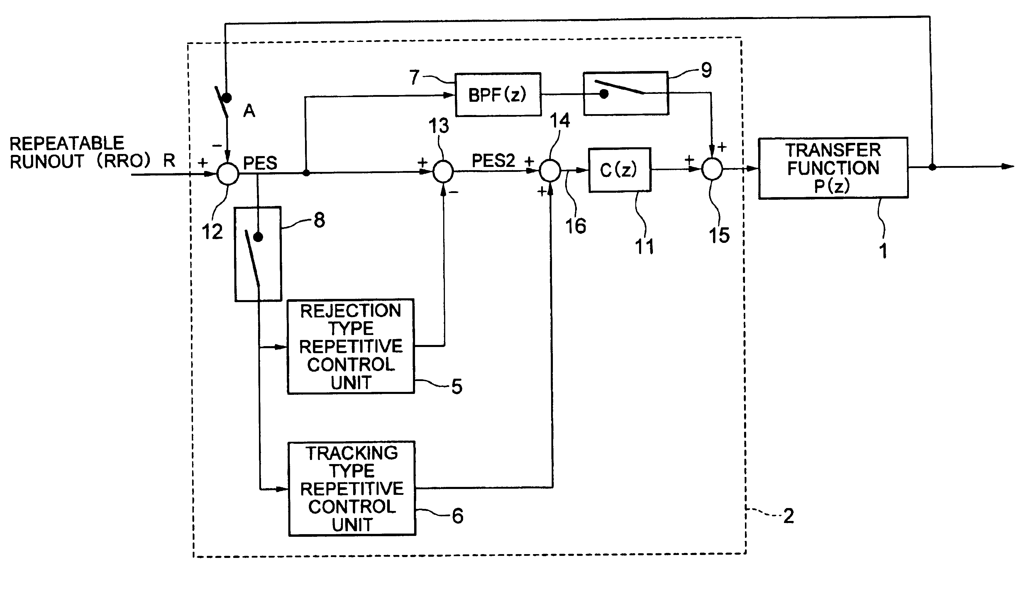
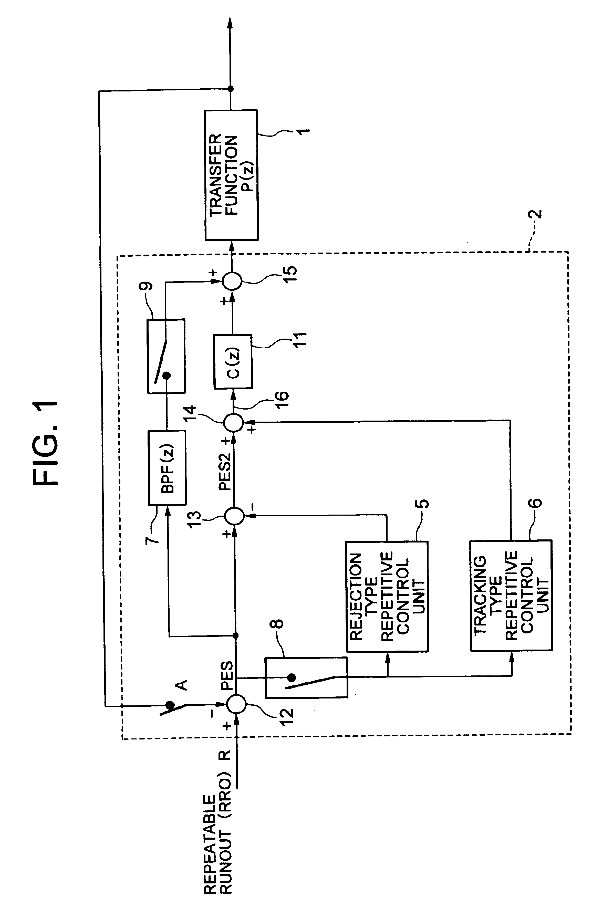
[0077]In the second embodiment mode, an output from a runout compensator 7 is added to an output from a following filter 11 by an adder 15. Thereafter, a total number of servo sector interrupts is counted by a counter. A switch 21 enters a position error signal PES into the rejection type repetitive control unit 23 in the case that this count value becomes larger than, or equal to a predetermined value.

[0078]A subtracter 25 subtracts the position error signal PES from an output signal derived from the rejection type repetitive control unit 23 so as to produce a modified position error signal PES2.

[0079]Similar to the switch 21, another switch 22 enters the modified position error signal PES2 into the tracking type repetitive control unit 24 in such a case that the above-explained count value becomes larger than, or equal to the predetermined value.

[0080]The rejection type repetitive control unit 23 owns an arrangement similar to that (explained in FIG. 6) of the rejection type repet...

first embodiment

[0082]As previously explained, even in such a case that the tracking type repetitive control unit 22 is coupled to the rejection type repetitive control unit 23 in the series manner, a similar effect to that of the first embodiment mode can be achieved, so that the modified position error signal PES2 can be improved.

[0083]As previously described, both the tracking type repetitive control unit which forces the magnetic heads to follow the low-order harmonics of the RRO components, and the rejection type repetitive control unit which the magnetic head not to respond to the high-order harmonics of the RRO components are provided in the following control loop. As a result, the data destruction occurred in the adjoining tracks can be avoided which is caused by that magnetic heads are unnecessarily followed to the high-order harmonics, and the positioning control of the magnetic head can be carried out in high precision.

[0084]Furthermore, such a band-pass filter having a peak at a frequen...


PUM


Abstract

In a disk drive, since high-frequency repeatable runout (RRO) components own low correlative relationships between adjoining tracks, a servo control system of a magnetic head is followed to the high-frequency RRO components, and thus, in the worst case, there is a possibility that data which have been previously recorded on these tracks are destroyed. To avoid this problem, both a tracking type repetitive control unit which is followed to low-frequency RRO components, and a rejection type repetitive control unit which cancels the high-frequency RRO components are provided in a following control loop in order that the following control system is not unnecessarily followed to the high-frequency RRO.

Description

BACKGROUND OF THE INVENTION[0001]The present invention is related to a positioning control of a disk drive capable of performing a positioning control of a head to a target track in a high speed and high precision.[0002]In magnetic disk drive corresponding to one of disk drive, magnetic heads are positioned onto data tracks formed on magnetic disks so as to read / write data from / in the data tracks.[0003]A sector servo system may constitute a major servo system, in which a positioning control of a magnetic head is carried out based upon a servo pattern formed by intermittently recording servo signals on a plane where data are recorded. As a consequence, a controller calculates a control input for controlling the magnetic head in synchronism with an interrupt signal produced by a servo sector so as to execute the positioning control of the magnetic head.[0004]A positioning control system for a magnetic disk drive may be mainly classified into a seek mode and a following mode. In the se...

Claims


Application Information

Patent Timeline
IPC IPC(8): G11B5/596G11B21/08G11B21/10
CPCG11B5/59627G11B21/10
Inventor INOUE, TAKAHIROITOU, KIYOTADASHISHIDA, KAZUHISAMATSUSHITA, SHINJIHORIGUCHI, TAKAO
Owner HITACHI GLOBAL STORAGE TECH JAPAN LTD
Why Eureka
Try Eureka