Linearized digital phase-locked loop method

a phase-locked loop and linear technology, applied in the field of linearized digital phase-locked loops, can solve the problems of inability to tolerate large input signal distortion, inability to truly “lock” the bang-bang system, and excessive jitter in the resulting recovered clock, so as to reduce the kinds of distortion associated with the bang-bang system, reduce data-dependent jitter, and reduce duty-cycle distortion

Inactive Publication Date: 2005-09-27
MONTEREY RES LLC
View PDF21 Cites 7 Cited by
  • Summary
  • Abstract
  • Description
  • Claims
  • Application Information

AI Technical Summary

Benefits of technology

[0009]The objects, features and advantages of the present invention include providing a method and / or architecture for implementing a linearized digital PLL that may (i) reduce the sorts of distortion associated with media induced effects, (ii) reduce duty-cycle-distortion (DCD) and / or (iii) reduce data-dependant-jitter (DDJ), (DCD and DDJ may be lumped into the single category of systematic jitter).

Problems solved by technology

As a result, a bang-bang system is never truly “locked”.
The bang-bang approach has the disadvantage of introducing excessive jitter in the resulting recovered clock since the clock is being shrunk or expanded at every edge.
Such detectors have an inability to tolerate large input signal distortion, such as the distortion that may be found at the end of typical wired media.

Method used


Image

  • Linearized digital phase-locked loop method
  • Linearized digital phase-locked loop method
  • Linearized digital phase-locked loop method

Examples


Embodiment Construction

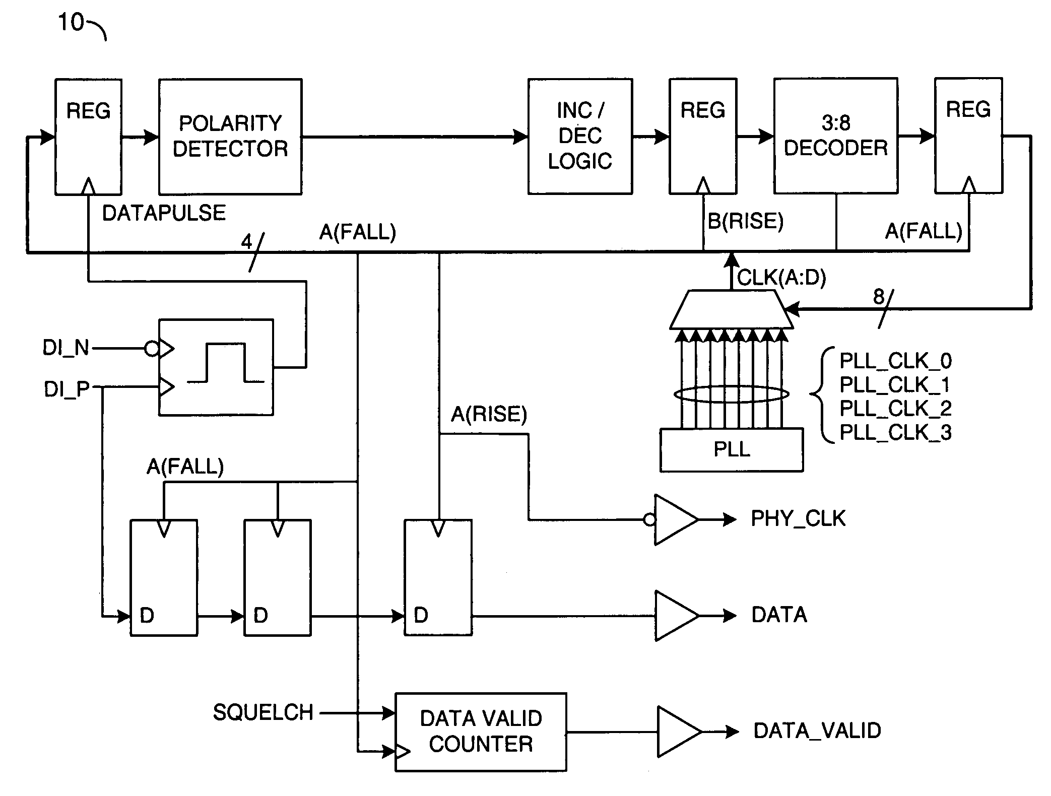
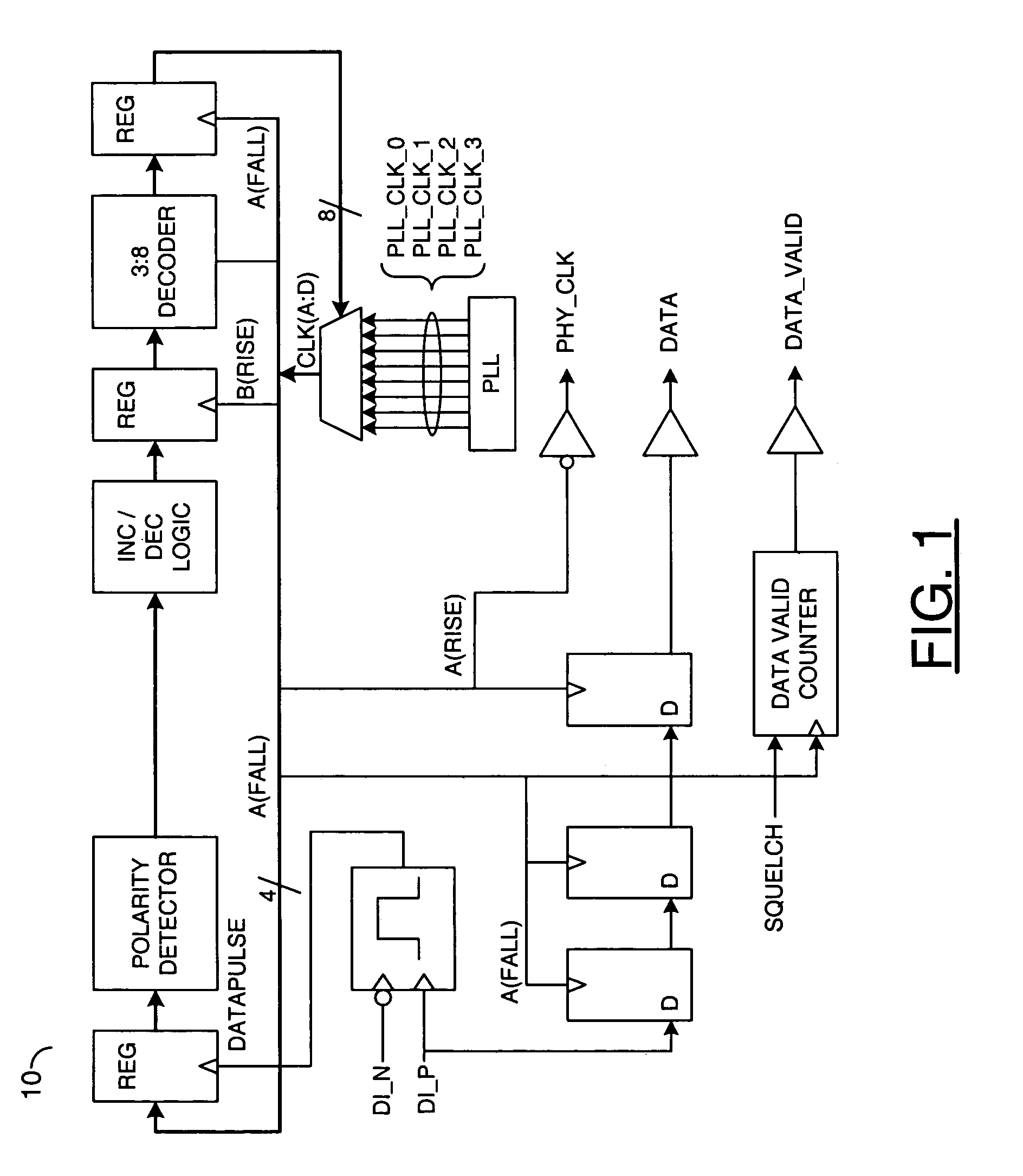
[0017]Referring to FIG. 3, a block diagram of a circuit 100 is shown in accordance with a preferred embodiment of the present invention. The circuit 100 generally comprises a logic block (or circuit) 102 and a control block (or circuit) 104. The circuit 104 may be implemented as a control circuit configured to adjust the frequency of an output clock.

[0018]The circuit 104 generally comprises a circuit 110, a circuit 112, a circuit 114 and a circuit 116. The circuit 104 may also comprise a number of memory elements 118a–118n and a number of buffers 120a–120n. The circuit 110 may be implemented as an edge detection circuit. The circuit 110 may present a signal (e.g., DATAPULSE) to the logic block 102. The signal DATAPULSE may be generated in response to a signal (e.g., DI—N) and a signal (e.g., DI—P). The signals DI—P and DI—N may be a complementary pair of signals. In one example, the circuit 110 may be configured to generate a pulse signal in response to a transition of a data signal...


PUM


Abstract

A method for synchronizing a clock signal to a data signal, comprising the steps of (A) detecting an edge of the data signal, (B) determining whether a position of the edge is within a zone and (B) if the edge is not within the zone, adjusting the clock signal towards the position of the edge.

Description

[0001]This application claims the benefit of U.S. Provisional Application No. 60 / 203,610, filed May 12, 2000 and is hereby incorporated by reference in its entirety.CROSS REFERENCE TO RELATED APPLICATIONS[0002]The present application may relate to co-pending application Ser. No. 09 / 745,660, filed Dec. 21, 2000, Ser. No. 09 / 747,281, filed Dec. 21, 2000, Ser. No. 60 / 203,677, filed Dec. 22, 2000, Ser. No. 09 / 747,262, filed Dec. 22, 2000, and Ser. No. 09 / 746,802, filed Dec. 22, 2000, which are each hereby incorporated by reference in their entirety.FIELD OF THE INVENTION[0003]The present invention relates to a method and / or architecture for implementing phase-locked loops (PLLs) generally and, more particularly, to a method and / or architecture for implementing linearized digital PLLS.BACKGROUND OF THE INVENTION[0004]Conventional approaches for implementing PLLs include the bang-bang approach which comprises taking snapshots of the phase error with respect to edges of incoming data. The ...

Claims


Application Information

Patent Timeline
Patent Type & Authority Patents(United States)
IPC IPC(8): H04L7/00H03L7/081H03L7/091H04L7/033
CPCH03L7/0814H03L7/091H04L7/0337
Inventor JORDAN, TIMOTHY D.LITTLE, TERRY D.DALMIA, KAMAL
Owner MONTEREY RES LLC
Why Eureka
Try Eureka