Fault location in a telecommunications network

a technology for fault location and telecommunications network, applied in the direction of substation equipment, electrical equipment, surveillance/monitoring/testing arrangements, etc., can solve problems such as physical damage and particular faults in parts of public telecommunications networks

Inactive Publication Date: 2005-09-27
BRITISH TELECOMM PLC
View PDF12 Cites 11 Cited by
  • Summary
  • Abstract
  • Description
  • Claims
  • Application Information

AI Technical Summary

Benefits of technology

[0013]By combining measurement of a fault length with a cable route infere...

Problems solved by technology

Since the components of the access network are those which are most exposed to the elements, this part of the public telecommunication...

Method used


Image

  • Fault location in a telecommunications network
  • Fault location in a telecommunications network
  • Fault location in a telecommunications network

Examples


Embodiment Construction

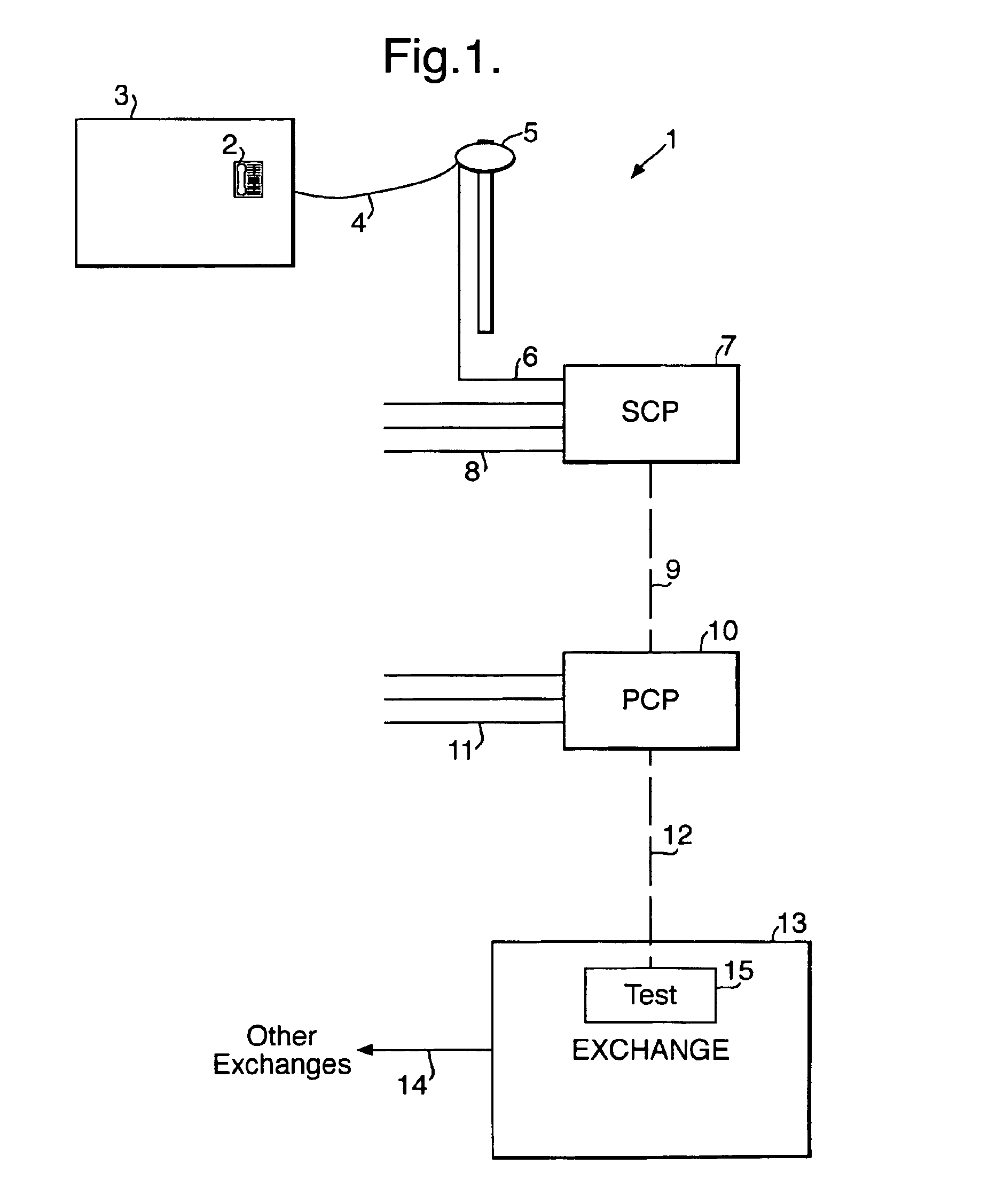
[0021]Referring to FIG. 1, a telecommunications network 1 includes a customer's terminal equipment 2 located, for example, at a customer's premises 3, a drop wire 4 connected between the customer's equipment and a pole mounted distribution point (DP) 5, a cable 6 extending from the distribution point 5 to a secondary cross-connection point (SCP) 7, further cables generally indicated at 8 extending from other distribution points (not shown) to the secondary cross-connection point 7, a cable 9 extending from the SCP 7 to a primary cross-connection point (PCP) 10, further cables generally indicated at 11 extending from other SCPs (not shown) to the PCP 10, a cable 12 extending from the PCP 10 to a local area exchange 13, a cable 14 linking the local area exchange 13 to other exchanges (not shown), and line test equipment 15 located in the exchange 13. The PCP 10 and the SCP 7 are for example street-side cabinets or underground junction boxes. As mentioned above, the part of the network...


PUM


Abstract

A fault is located along a telecommunications line between the network terminating equipment and the local exchange by measuring a change in the capacitance of the line when compared with the capacitance under normal operating conditions. A geographical information system is used to plot all possible routes for the line between the terminating equipment and the exchange, and the most probable route is selected based on the known positions of nodes along the line, such as pole mounted distribution points and streetside cabinets. The distance of the fault along the line is then plotted along the most probable route to determine an accurate fault location, which is given to a field technician as the location of the nearest premises or a grid reference.

Description

[0001]This application is the US national phase of international application PCT / GB01 / 01422 filed 29 Mar. 2001 which designated the U.S.BACKGROUND OF THE INVENTION[0002]1. Field of the Invention[0003]This invention relates to the field of fault location in a telecommunications network.[0004]2. Related Art[0005]A conventional public telecommunications network is generally described as having two parts, namely a core network and an access network. The access network is that part of the network which extends from the terminal equipment, for example a customer's telephone or a public call box, to a local exchange. The core network includes the local and trunk exchanges.[0006]In a conventional access network, each communications line is formed from a pair of copper wires. Typically, each pair of wires pass through a series of nodes between the local exchange and the terminal equipment. Examples of such nodes are primary cross-connect points, secondary cross-connect points, distribution p...

Claims


Application Information

Patent Timeline
IPC IPC(8): H04M3/30H04M3/28H04M3/08
CPCH04M3/085H04M3/30H04M3/305
Inventor DRURY, IAN RO'CONNOR, CHARLES DCHATTELL, ANDREW DLOGAN, HILARY PTHORPE, NEIL ALOWNDES, GEOFFREY RLUNT, NICHOLAS
Owner BRITISH TELECOMM PLC
Why Eureka
Try Eureka