
Creating geometric model descriptions for use in machine vision inspection systems

a machine vision inspection and geometric model technology, applied in the field of machine vision inspection, can solve the problems of expensive and impractical manual modeling process, defective objects, laborious and time-consuming refinement process,

Inactive Publication Date: 2005-09-27
COGNEX CORP
View PDF22 Cites 25 Cited by
  • Summary
  • Abstract
  • Description
  • Claims
  • Application Information

AI Technical Summary

Benefits of technology

[0009]An object of the invention is to provide processes and mechanisms that allow a user to generate accurate geometric models of objects. Such processes and mechanisms may be designed so that geometric models are generated directly from object images, and may be provided with features that ensure the quality of the generated models.

Problems solved by technology

If the inspected object deviates from the geometric model of the object by more than a predefined inspection threshold, that may indicate that the object is defective.
The refinement process is tedious, labor intensive, and time consuming.
For an application in which the objects to be modeled change from time to time, such a manual modeling process is expensive and impractical.

Method used


Image

  • Creating geometric model descriptions for use in machine vision inspection systems
  • Creating geometric model descriptions for use in machine vision inspection systems
  • Creating geometric model descriptions for use in machine vision inspection systems

Examples


Embodiment Construction

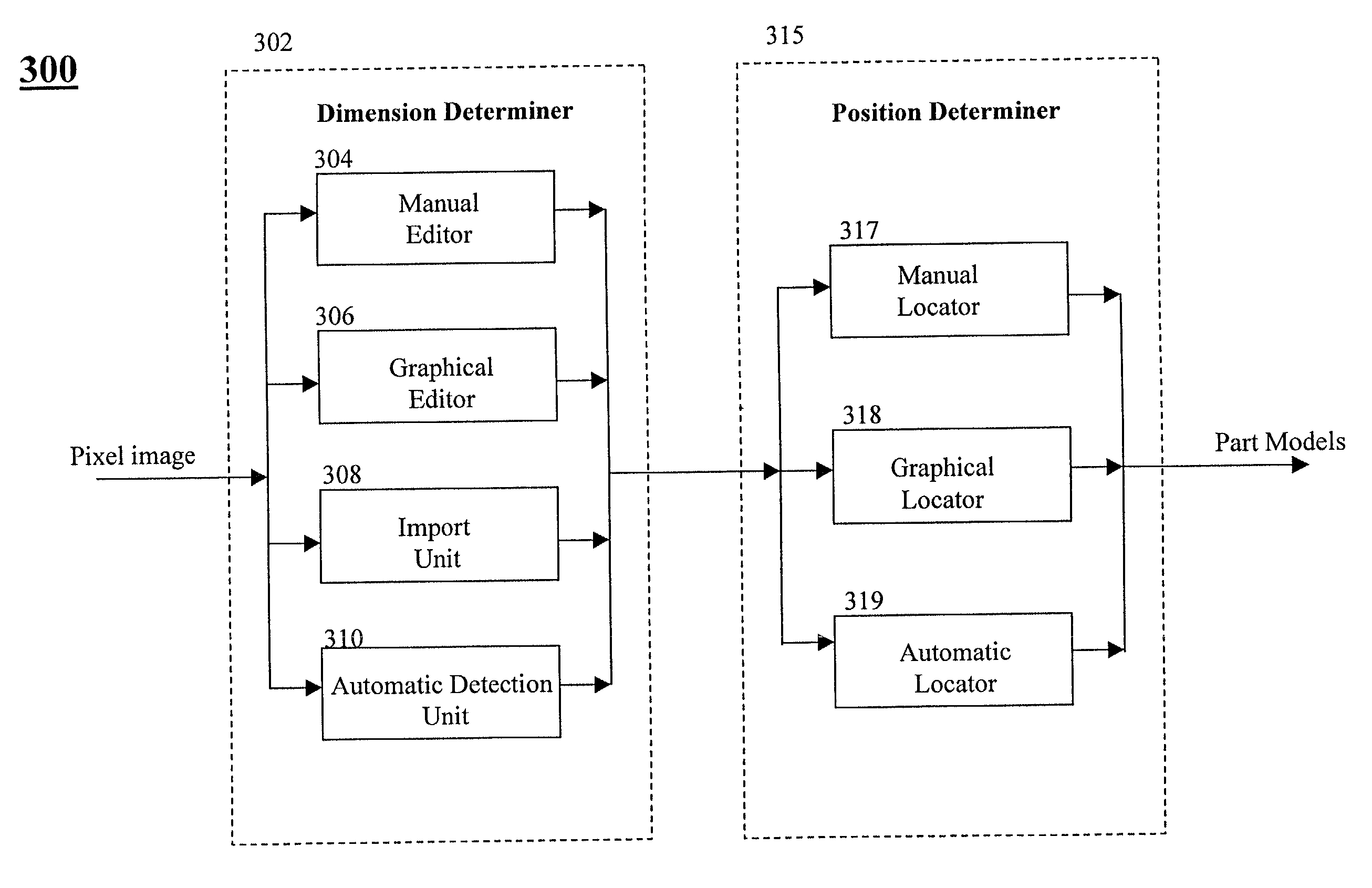
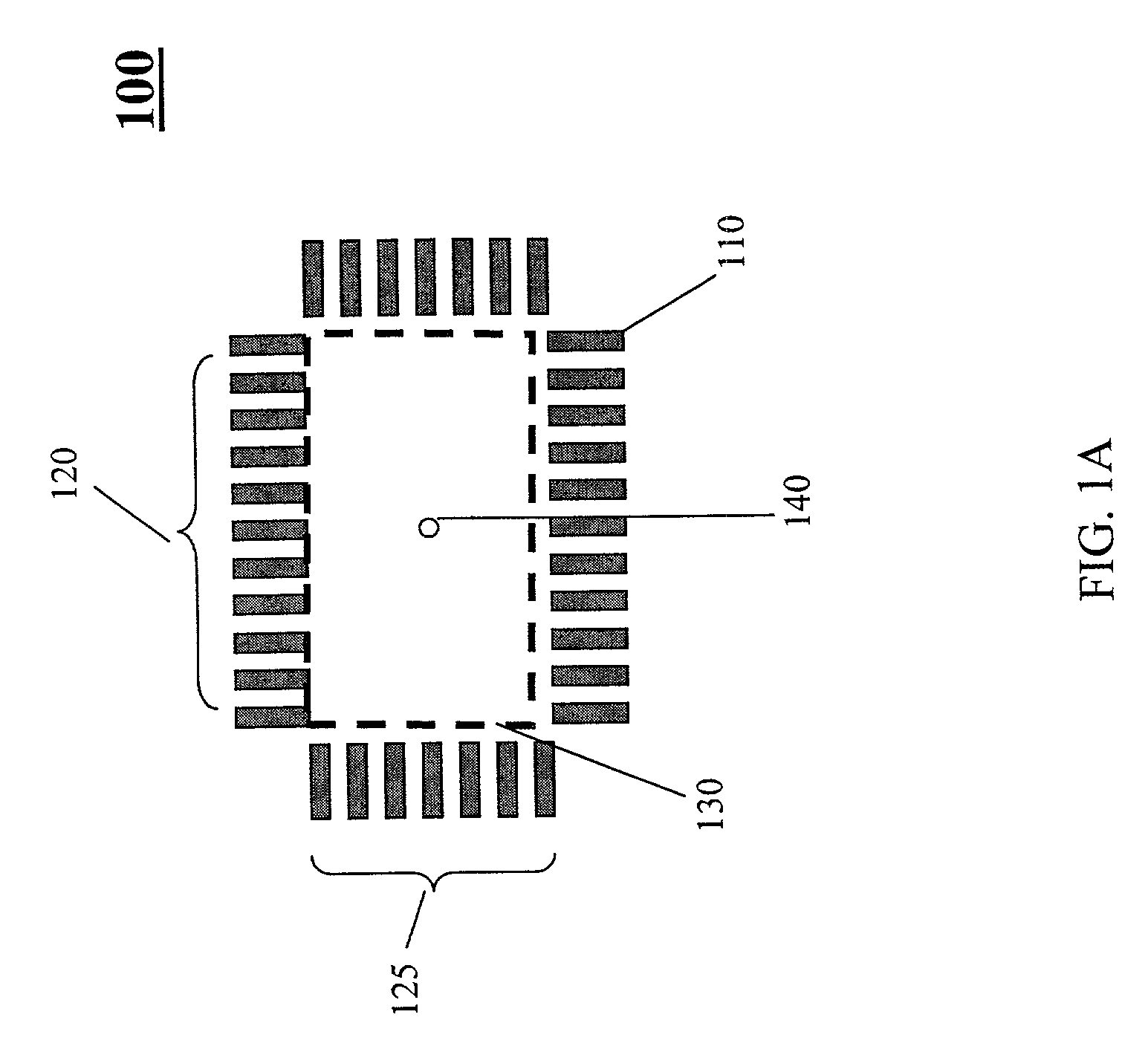
[0027]An embodiment of the invention is illustrated that is to be used to create a geometric model of an object from one or more images of the object. The illustrated embodiment allows a user to quickly create and test geometric models using manual, graphical, and / or automatic tools. The geometric models may be used in machine vision inspection systems.

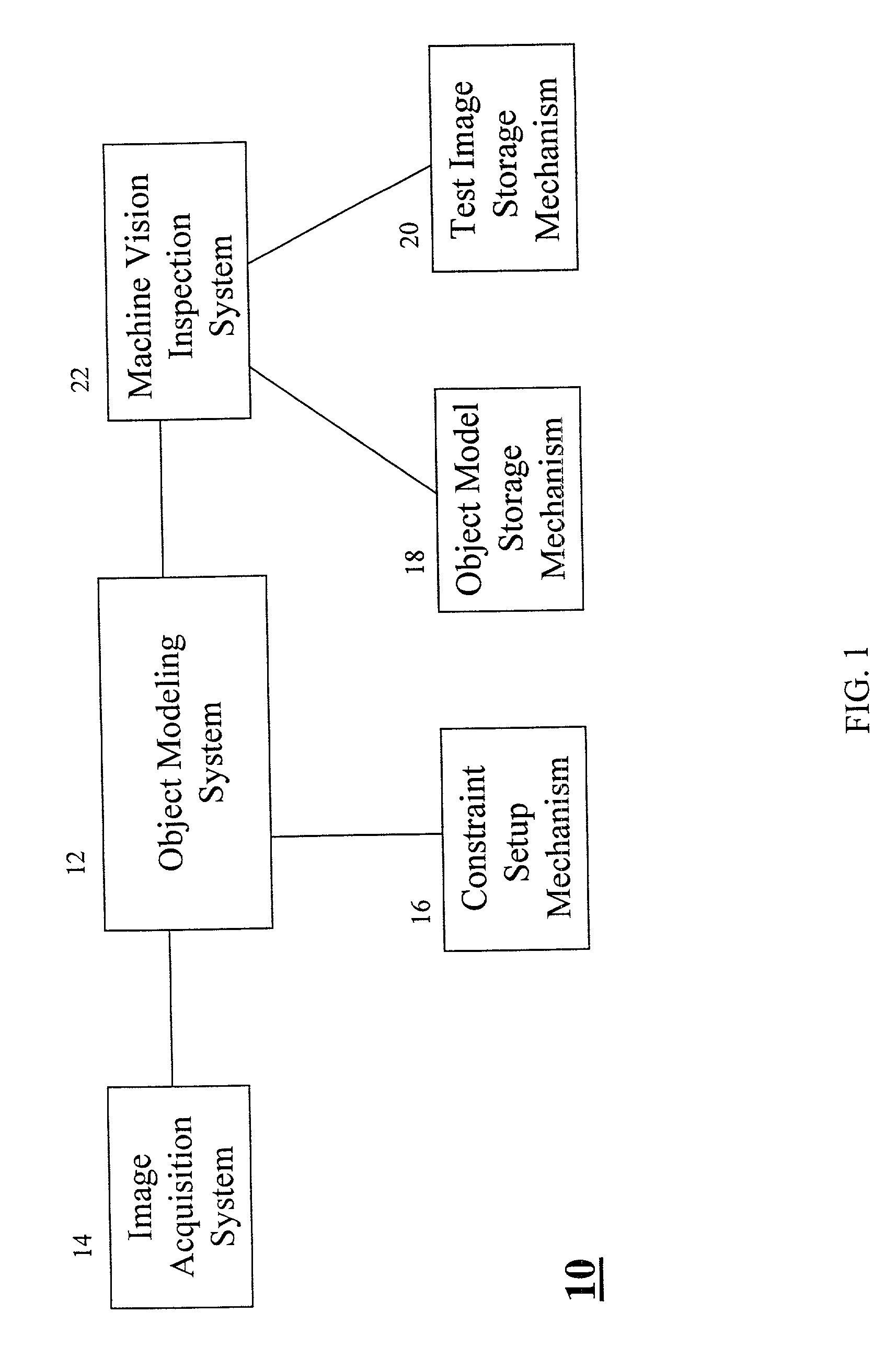
[0028]FIG. 1 shows a geometric model generation system 10. The illustrated geometric model generation system 10 comprises an object modeling system 12, an image acquisition system 14, an object model storage mechanism 18, a test image storage mechanism 20, a constraint setup mechanism 16, and a machine vision inspection system 22. Image acquisition system 14, in the illustrated embodiment, may comprise, for example, a digital camera or any type of image acquisition device which will create a pixel image of an object. In addition, image acquisition system 14 may comprise a calibration unit for calibrating the image coordinate system wi...


PUM


Abstract

A method and system create a geometric object model for use in machine vision inspection. A pixel image representation of an object is acquired. Based on this pixel image representation, part models for the parts of the object are generated. Each part model corresponds to a different part of the object. From the part models of the object, a model for the entire object can be created. Using this created object model, a test inspection is performed on a set of test images, and each of the test images is associated with a set of known inspection measurements. The test inspection produces a set of testing inspection measurements. If the test inspection yields satisfactory performance, the object models created are stored.

Description

PRIORITY APPLICATION DATA[0001]Priority is claimed to Provisional Application No. 60 / 205,595, filed May 17, 2000, the content of which is hereby incorporated herein by reference in its entirety.COPYRIGHT NOTICE[0002]This patent document contains information subject to copyright protection. The copyright owner has no objection to the facsimile reproduction by anyone of the patent document or the patent disclosure, as it appears in the U.S. Patent and Trademark Patent Office files or records but otherwise reserves all copyright rights whatsoever.BACKGROUND[0003]1. Field of the Invention[0004]Aspects of the present invention relate to machine vision inspection. Other aspects of the present invention relate to creating geometric object models for use in machine vision inspection systems.[0005]2. Description of Background Information[0006]For purposes of the disclosure contained herein, a geometric model of an object comprises parameter representations of the geometry of the object. For ...

Claims


Application Information

Patent Timeline
IPC IPC(8): G06K9/00G06T7/00
CPCG06T7/001G06T2207/30148
Inventor BACHELDER, IVAN A.CHANG, YUNTOSA, YASUNARIGOPALAKRISHNAN, VENKATFIX, RAYMONDMILLIGAN, ROBHUNT, THERESEROBERTS, KAREN
Owner COGNEX CORP
Learn More