Method for providing multiple points of connectivity to subscribers of wireless communication networks

a wireless communication network and wireless communication technology, applied in the field of multiple point of connectivity for subscribers of wireless communication networks, can solve the problems of increasing complexity, changing the type of services and resources provided to subscribers, and information being transmitted and received by an mn having access to a data network is often quite sensitive to interruptions in service, and achieves the effect of little or no loss of data

Inactive Publication Date: 2005-09-27
LUCENT TECH INC
View PDF16 Cites 27 Cited by
  • Summary
  • Abstract
  • Description
  • Claims
  • Application Information

AI Technical Summary

Benefits of technology

[0024]The network interface of the method of the present invention can be established by system equipment. In such a case, a data service entity establishes the network interface by sending a message (e.g., an origination message) to its network controlling element to establish a network interface. A network controlling element can also establish a network interface by generating data that route communication channels associated with a particular MN to other network controlling elements. After the network interface is established, information received by the network controlling element from the data network (via the data service entity) is routed as per the dictates of the established network interface. Therefore, the network interface of the method of the present invention allows an MN to have simultaneous connections to different data service entities of a communication network and thus provides multiple point connectivity to different networks.
[0025]In a preferred embodiment of the method of the present invention, the network interfaces allow an MN having simultaneous access to different network attachment points controlled by different network controlling elements to be handed off from one network attachment point to another network attachment point with relatively little or no loss of data being exchanged between the MN and the corresponding data service entities. The MN first gains access to the wireless network through a first network attachment point coupled to a first data service entity via a first network controlling element.
[0027]While the MN is establishing the second set of communication channels with the second data service entity via the second network attachment point and the second network controlling element as per the handoff procedure, information being exchanged between the MN and the first data service entity is routed from the first network controlling element to the second network controlling element (or vice versa) in accordance with the dictates of network interface of the method of the present invention. Thus, prior to the completion of the handoff, the MN is able to exchange information with the first and second data service entities. Upon completion of the registration and initialization procedures with the second data service entity, the MN terminates the first set of communication channels between itself and the second network controlling element. The second network controlling element then releases the connection to the first network controlling element. Exchange of information between the MN and the second data service entity is now achieved via the second network controlling element. The handoff is thus executed with relatively little or no loss of data.

Problems solved by technology

As the use and popularity of these networks have increased, the type of services and resources provided to subscribers have changed and increased in complexity.
Wireless communication networks such as the one depicted by FIG. 1 suffer from the limitation that, for a particular MN, only one access point to a data network at a time is allowed.
Also, information being transmitted and received by an MN having access to a data network is often quite sensitive to interruptions in service caused by handoffs being performed by the wireless communication network.
The interruptions are often due to loss of information that occur during handoffs.
Particular types of information—such as information associated with multimedia applications—are especially sensitive to loss of information that can occur to handoffs.
A handoff is a well known procedure whereby a migrating MN being served by a particular BTS is physically located such that the BTS cannot provide adequate quality of service to the MN.
During such transference of data, service to the migrating MN is interrupted causing information being transmitted or received by the MN to be lost.
There are two types of interruptions that cause information loss.
This second interruption is much longer and is the cause of the majority of loss of information for the mobile.
When the mobile or network detects that the quality of the radio signal from the first set of BTSs has degraded to a point that further degradation would cause an unsatisfactory communication quality or even loss of a session, the mobile then establishes a second and identical session with a second set of BTS's under the control of a second BSC coupled to a second PDSN.
Most importantly, the cost of adding new hardware to subscriber and system equipment is most likely quite prohibitive to subscribers and system providers.

Method used


Image

  • Method for providing multiple points of connectivity to subscribers of wireless communication networks
  • Method for providing multiple points of connectivity to subscribers of wireless communication networks
  • Method for providing multiple points of connectivity to subscribers of wireless communication networks

Examples


Embodiment Construction

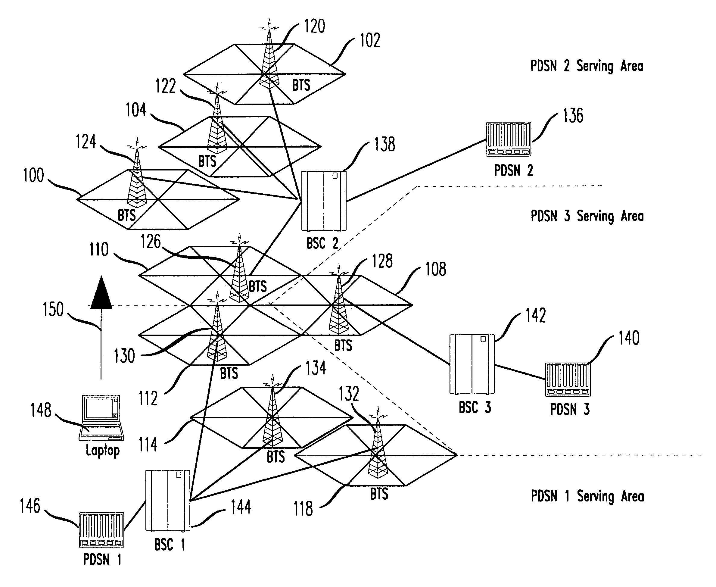
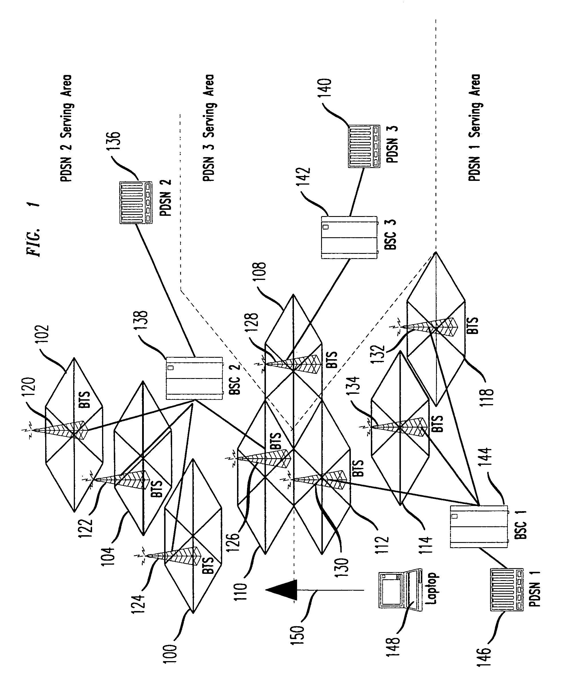
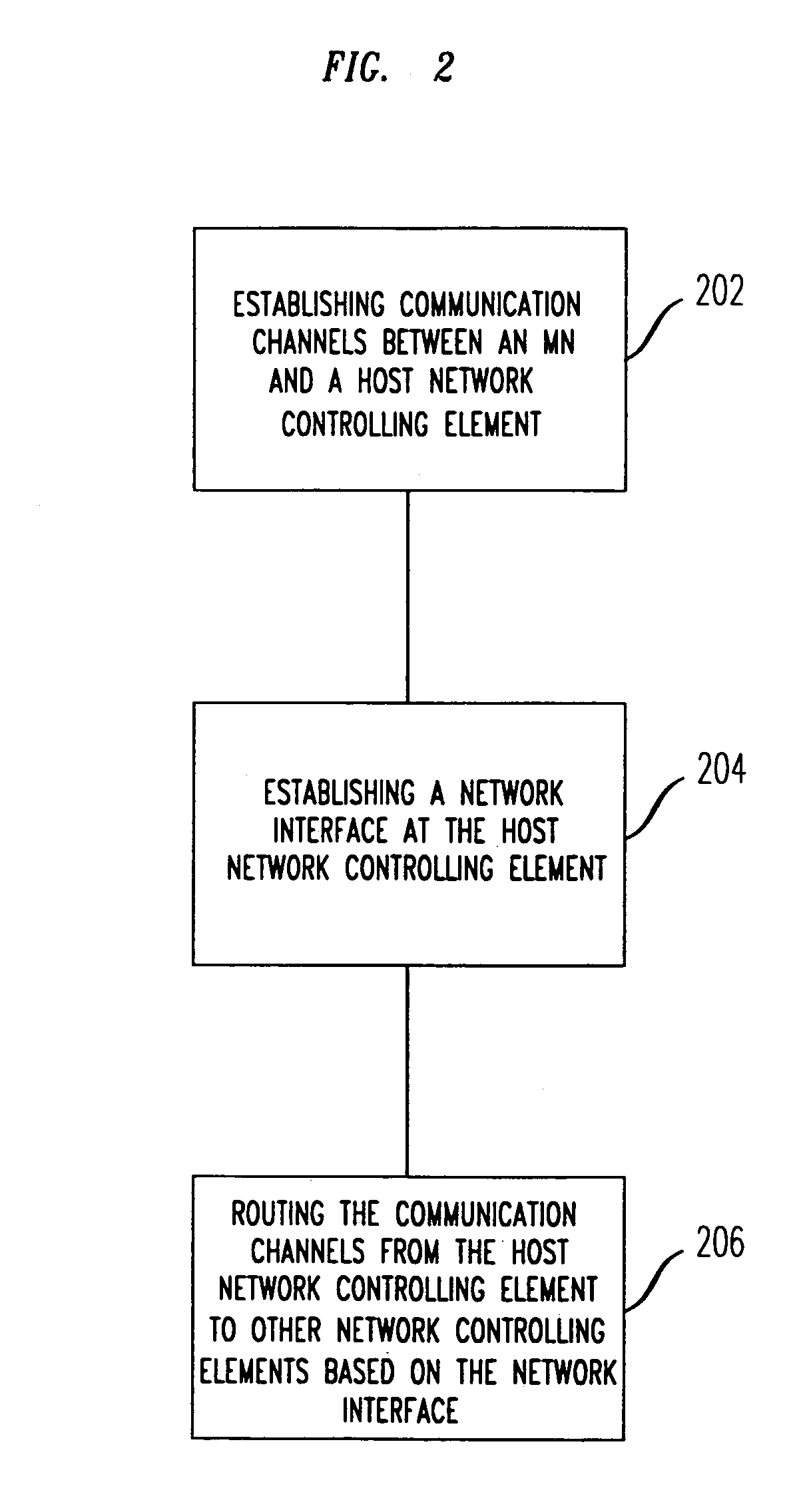
[0030]The present invention provides network interfaces between network controlling elements of a communication network so as to allow information being conveyed through multiple channels between an MN and a network attachment point to be routed to multiple network controlling elements and thus multiple data service entities of the communication network. The data service entities are typically coupled to other communication networks and thus the network interfaces enable multiple point connectivity between and MN and various other communication networks. The network interface of the method of the present invention is based on and is compatible with communication protocols and standards that govern how information is exchanged between network controlling elements of the communication network. For example, for some Asynchronous Transfer Mode (ATM) networks, the network interface of the method of the present invention would be based on and is compatible with the Q.2931 signaling contro...


PUM


Abstract

A method for allowing a mobile of a wireless communication simultaneous access to multiple data networks coupled to the wireless communication network. A network interface is created between network controlling elements, such as Base Station Controllers, of the wireless communication network. The network interface allows various communication channels established by the mobile to be routed to network controlling elements that are coupled to the various data networks. Information from various established communication channels are routed between various network controlling elements. Thus, a mobile is able to communicate simultaneously with different data networks. The network interface also allows handoffs to be executed with virtually no interruptions and no loss of information being exchanged between the mobile and system equipment involved in the handoff.

Description

BACKGROUND OF THE INVENTION[0001]1. Field of the Invention[0002]The present invention provides a method for providing subscribers of a wireless communication network with multiple points of connectivity without adding additional hardware to the network or to the subscriber's mobile.[0003]2. Description of the Related Art[0004]Wireless communication networks have established well known techniques that provide multiple subscribers access to these networks. Some of these techniques include Code Division Multiple Access (CDMA), Time Division Multiple Access (TDMA) and Frequency Division Multiple Access (FDMA). Also, various combinations of these techniques (and other multiple access techniques) are used to provide access to subscribers. As the use and popularity of these networks have increased, the type of services and resources provided to subscribers have changed and increased in complexity. The resources are the system equipment (e.g., radio transmitters, radio receivers, processing...

Claims


Application Information

Patent Timeline
Patent Type & Authority Patents(United States)
IPC IPC(8): H04Q7/30H04Q7/22H04Q7/38H04L12/28H04L12/56H04M3/00H04W92/22
CPCH04W92/22H04L12/28H04W40/26
Inventor HILLER, THOMAS LLOYDMARKS, ROBERT JERROLDMCCANN, PETER JAMES
Owner LUCENT TECH INC
Why Eureka
Try Eureka