[0008]The object of the present invention is to provide an
improved method and a suitable
system for discharging suspended microparticles from a fluidic microsystem, which in particular is robust, has a simple design and guarantees rapid discharge of particles without any negative effect on the function of the microsystem, in particular the flow conditions prevailing there, and can be adapted easily to different applications. This invention attempts in particular to achieve a discharge of microparticles with a fluid flow from microsystems or microcapillary systems with little or no loss of microparticles.
[0011]The method of discharging the fluid flow is a metering (dosing) method in which the density of the microparticles and their provision at the end of the conduction element are adjusted in a predetermined manner. This invention makes it possible for the first time to adjust the velocities of flow required in operation of a fluidic microsystem freely and independently of one another. In the microsystem, there is a relatively low flow velocity of the
microparticle suspension (see above). After output from the microsystem, the flow velocity should be increased in a certain manner, depending on the application. In contrast with the enveloping flow principle of
hydrodynamic focusing, the velocities of flow of the fluid flow and the output flow have comparable values. The flow velocity of the output flow may be lower than, the same as or greater than the flow velocity of the fluid flow. However, no such great differences in velocity are established as in focusing (e.g., factor off a few thousand or more). In typical applications, the quotient of the velocities of flow of the fluid flows and output flows is in the range of 0.1 to 500, preferably less than 300. The
inertia of the suspension dosage according to this invention in such flow ratios is preferably especially low. The particle-free volume of the output flow is adjustable individually especially after each individual
microparticle has passed by with the fluid flow. The particle sequence in the fluid flow typically includes one microparticle in a
time range of approx. 100 ms to 1 s. Such time ranges make it possible to adjust the flow velocity of at least one output flow. Depending on the task involved, individual particles can be removed from the microsystem more quickly or more slowly. Thus, a problem in microsystem technology which has been unsolved in the past has now been solved for the first time.
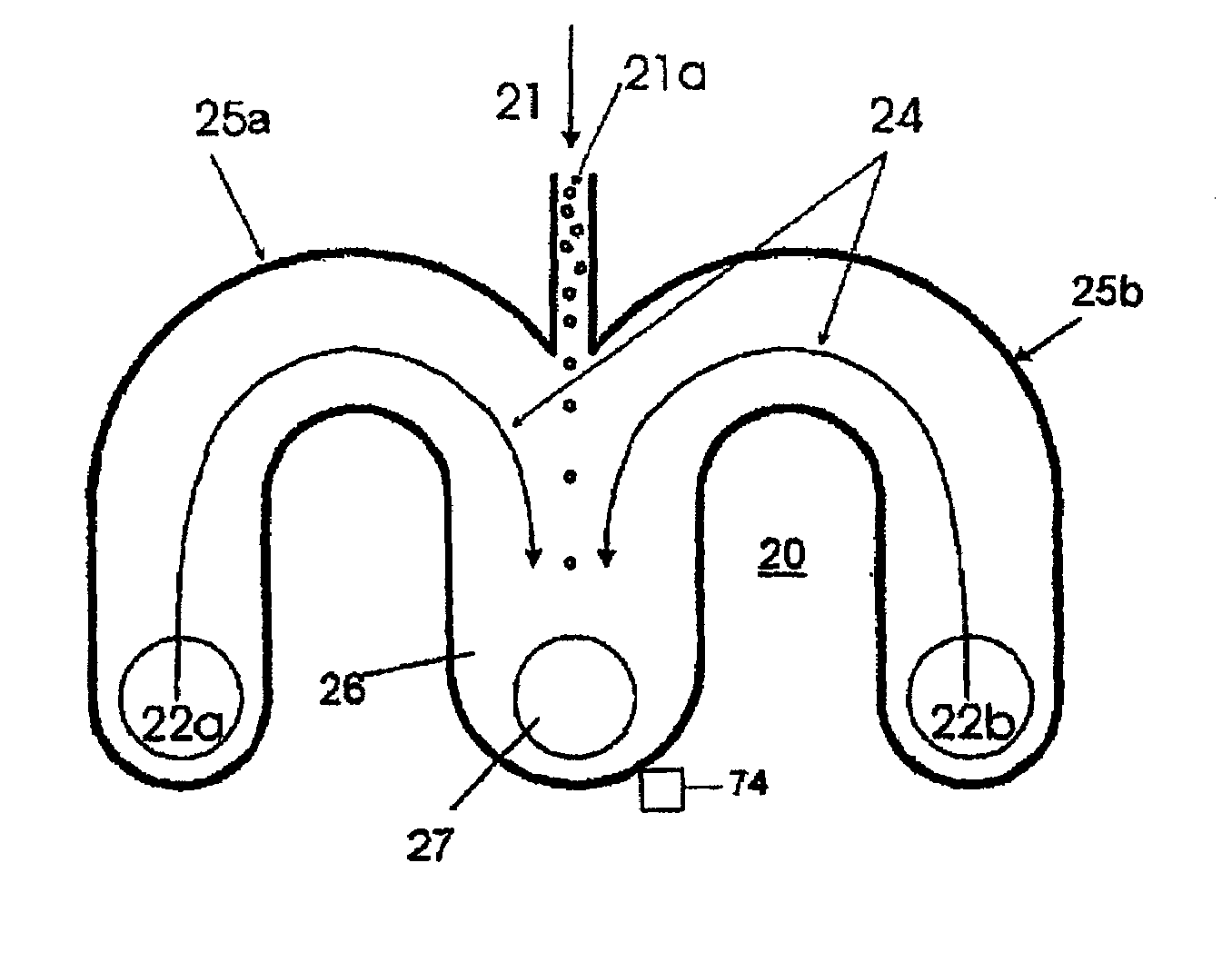
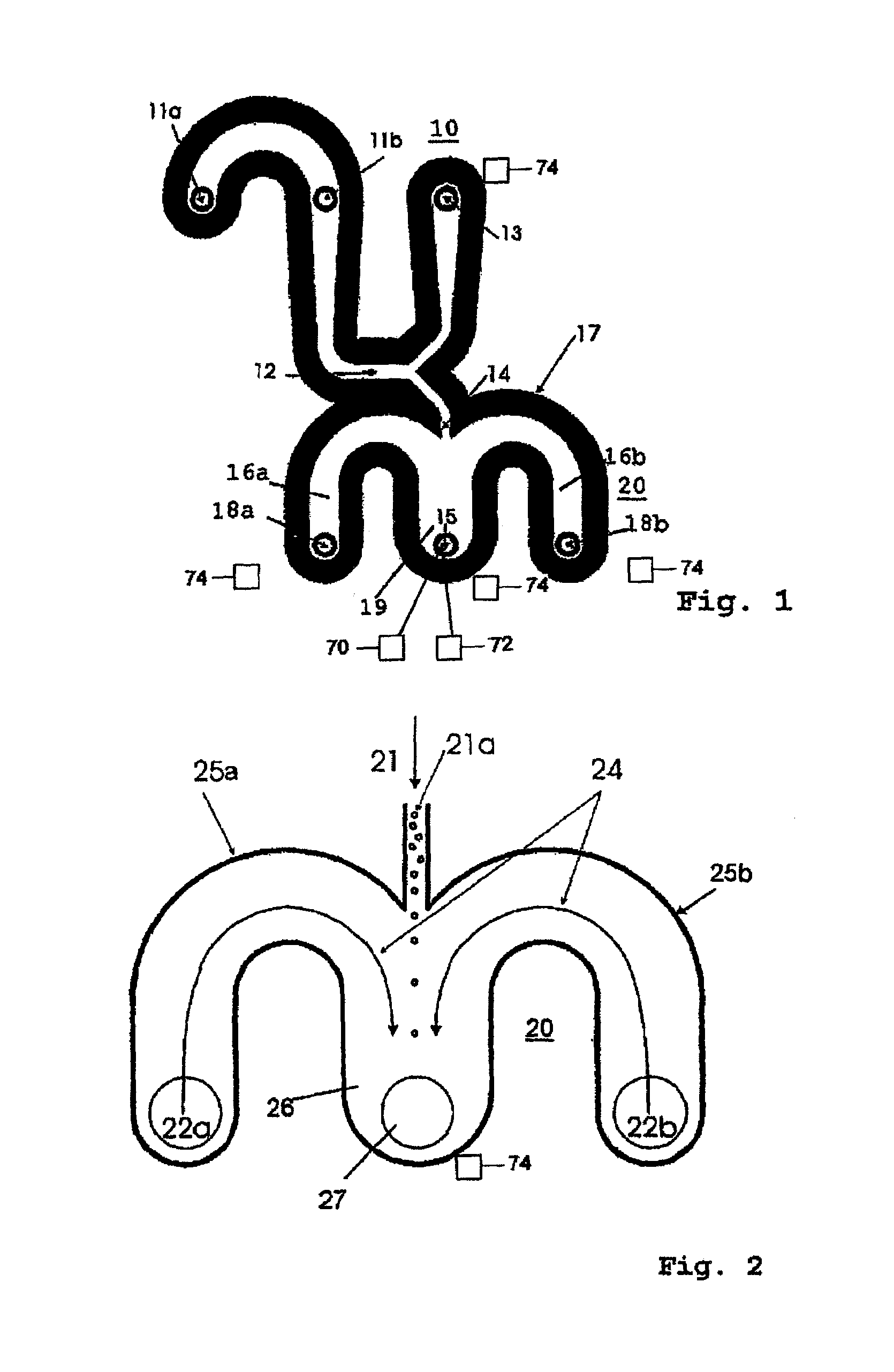
[0017]According to a preferred embodiment of the microsystem, the at least one output channel forms a side influx which opens into the discharge channel or at the end of the discharge channel. Since there is no focusing of particles, it is possible with
advantage to omit the ring-shaped influx which is formed in
hydrodynamic focusing and instead to provide a planar embodiment of the channel structure. There are advantages in particular with respect to the simple design and miniaturizability of the flow
output device. When multiple output channels are provided, they are preferably also arranged in one plane as lateral influxes. Several flow output devices can also be arranged asymmetrically and / or offset with a distance from one another in the direction of flow, depending on their tasks.
[0021]This invention offers the following advantages. Due to the use of an output flow at the outlet of a microsystem, the suspended microparticles, e.g., biological cells or
cell constituents, synthetic particles or composite particles with biological and synthetic components, macromolecules or aggregates of macromolecules can be removed from the microsystem with little or no loss. The flow rate in the output flow can be increased without any interfering influence on the flow velocity in the microsystem upstream from its outlet. Due to the increase in the flow velocity of the
particle suspension after discharge from the microsystem, the risk of interactions between the particles and the channel walls is reduced. For example,
cell adhesion can be prevented. This invention is applicable to
advantage especially at low velocities of flow in the microsystem in the range of 1 μm / s to 10 mm / s, for example. According to this invention, the velocity of the
particle suspension in discharge from the microsystem can be increased as greatly as possible for effective and rapid discharge of the particles from the microsystem. For example, a
peristaltic pump is suitable for this purpose. In one example, the velocity of the suspension could be accelerated from 1-20 μl / h to 70 to 280 μl / h. At higher velocities of flow, however, pulsation of the
peristaltic pump acts on the flow of the particles upstream from the flow
output device (e.g., disturbance in maintaining the microparticles in
dielectric field cages).
[0022]Use of a hydrodynamic pump principle is more suitable for rapid discharge of the particles. For example, the liquid may be sent to the flow output device from a liquid-filled reservoir which is acted upon at a low excess pressure applied via a compressor with a
throttle valve connected to it. Thus, much higher flow rates, namely up to 25 μl / s (with a
working range of up to 0.8 bar excess pressure), or typically 2 μl / s (with a
working range of up to 0.1 bar excess pressure) can be achieved in the microsystem without any negative effect on the incoming
particle suspension.

