
Geolocation using enhanced timing advance techniques

a technology of enhanced timing advance and geolocation, applied in the direction of direction finders using radio waves, instruments, wireless communication, etc., can solve the problems of inability to backward compatibility of e-otd and agps methods from the perspective of second generation mobile-stations, and the average error associated with the cell/sector id can be quite large, so as to achieve the effect of accurate location and location accuracy

Inactive Publication Date: 2005-09-27
LUCENT TECH INC
View PDF6 Cites 67 Cited by
  • Summary
  • Abstract
  • Description
  • Claims
  • Application Information

AI Technical Summary

Benefits of technology

[0007]The aforementioned problems of backward compatibility and location accuracy can be overcome or improved using timing advance principles and signal strength measurements. In one embodiment, the present invention comprises the steps of determining a set of candidate locations for the mobile-station based on a timing advance value associated with the mobile-station, and determining a location of the mobile-station using the set of candidate locations and signal strength measurements associated with same cell-neighboring sectors or different cell-neighboring sectors. Advantageously, timing advance values and signal strength measurements are readily available in most second generation wireless communication networks, thus, no new hardware or software are required in existing second generation mobile-stations. Additionally, the present invention uses timing advance values to select an area smaller than cells and sectors in which mobile-stations may be located and signal strength measurements to specify a location within the selected area, thereby obtaining a more accurate location of the mobile-stations than the Cell / Sector ID method.

Problems solved by technology

Depending on the radius of cell 10, the average error associated with the Cell / Sector ID can be quite large and, thus, unacceptable.
However, the E-OTD and AGPS methods are not backward compatible from the perspective of second generation mobile-stations.

Method used


Image

  • Geolocation using enhanced timing advance techniques
  • Geolocation using enhanced timing advance techniques
  • Geolocation using enhanced timing advance techniques

Examples


first embodiment

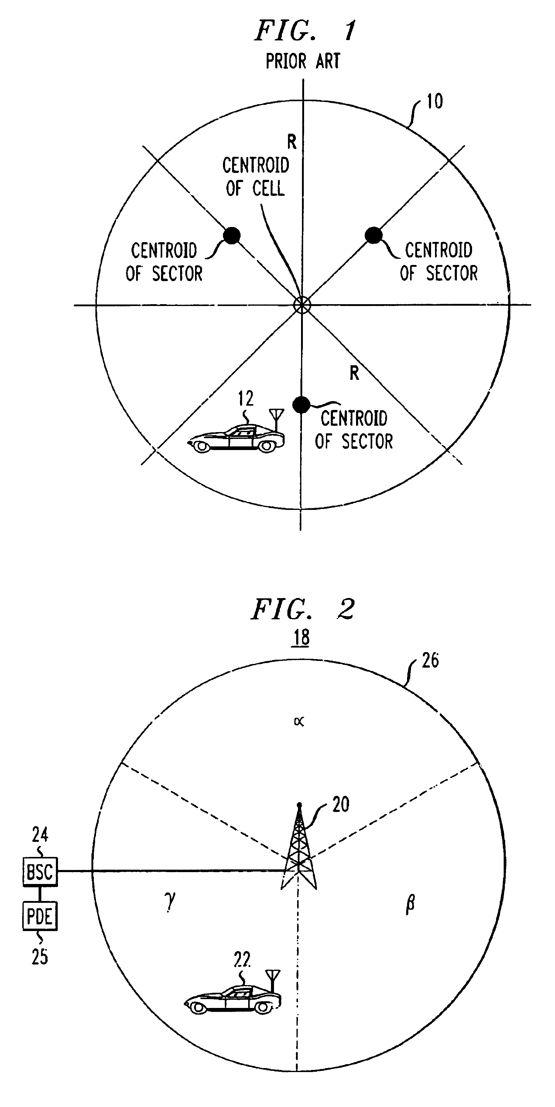
[0029]In step 430, the received beacon frequency signal strength measurements associated with same cell-neighboring sectors are used to determine a location for MS 22. In this embodiment, there are six candidate locations for MS 22 within TA belt 28. These six candidate locations are determined using the sector ID, TA value and information associated with the base station, and are positioned approximately at the intersections of TA belt 28 and center and sector dividers of the cell. Sector dividers are defined by the radio frequency (RF) coverage of each cell and may not be straight lines. The sector dividers may, however, be approximated as straight lines using conventional least-square-estimation method. Center dividers are lines associated with sectors that extend outward from the center of a cell towards the edge of the cell approximately dividing the associated sector in half. FIG. 6 depicts these six candidate locations 61, 62, 63, 64, 65 and 66 for MS 22 within TA belt 28. Th...

second embodiment

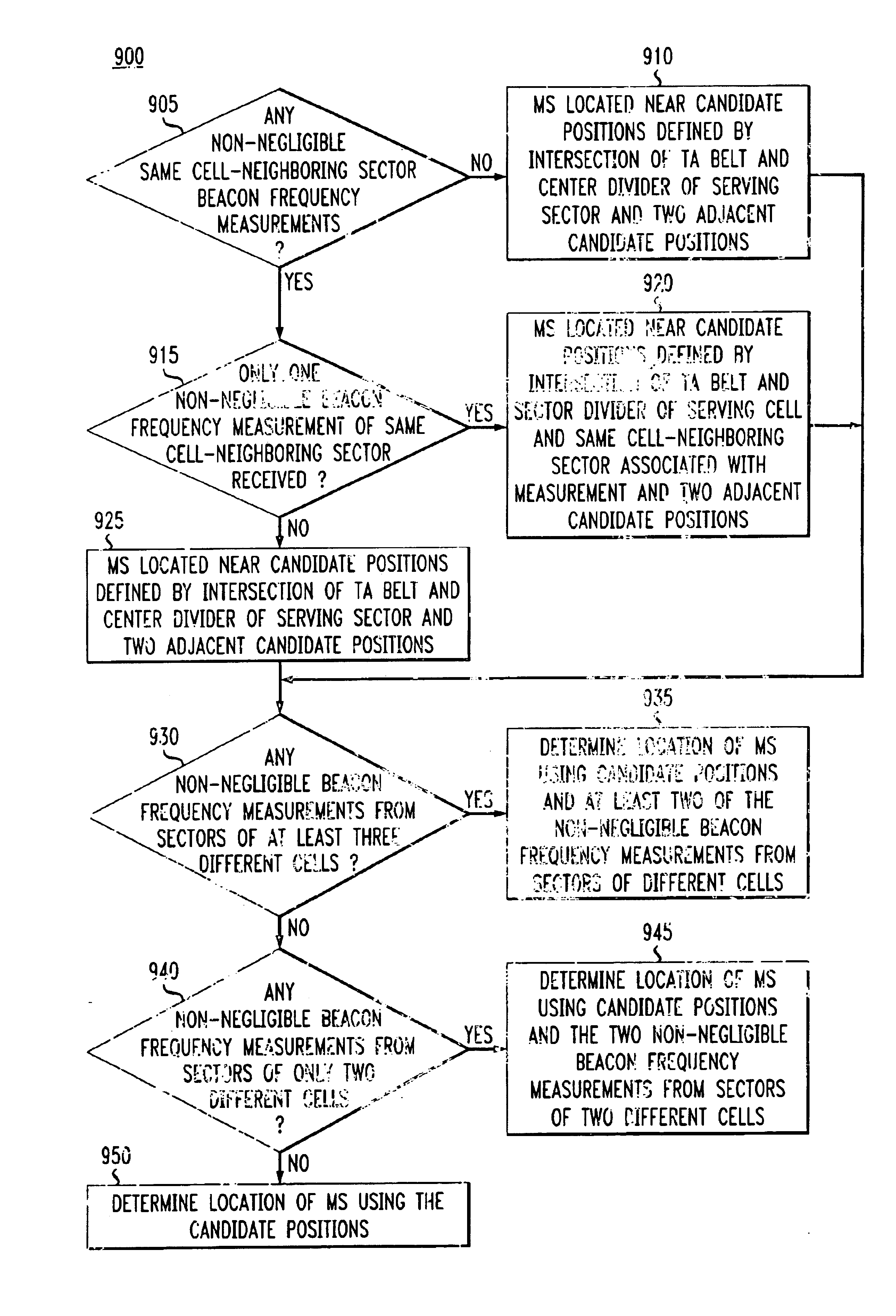
[0034]FIG. 9 depicts a flowchart 900 illustrating step 430. In step 905, PDE 25 determines if any beacon frequency signal strength measurements associated with any same cell-neighboring sectors were received in step 410. If PDE 25 did not receive any non-negligible beacon frequency signal strength measurements associated with any same cell-neighboring sectors, then PDE 25 determines, in step 910, that MS 22 is located at or near one of three candidate locations: the candidate location defined by the intersection of TA belt 28 and the center divider of the serving sector indicated by the received sector ID, and the two adjacent candidate locations. For example, suppose MS 22 is currently being served by sector β and no beacon frequency signal strength measurements associated with any same cell-neighboring sectors were received by PDE 25, then PDE 25 would be located at or near candidate locations 64, 69 and 70.

[0035]Otherwise, flowchart 900 continues to step 915 where PDE 25 determin...


PUM


Abstract

A method of geolocation that is backward compatible and more accurate than the well-known Cell / Sector ID method is provided. The geolocation method provided comprises the steps of determining a set of candidate locations for the mobile-station based on a timing advance value associated with the mobile-station and determining a location of the mobile-station using the set of candidate locations and signal strength measurements associated with same cell-neighboring sectors or different cell-neighboring sectors.

Description

FIELD OF THE INVENTION[0001]The present invention relates generally to systems for locating wireless communication devices and, in particular, to wireless location systems using timing advance techniques.BACKGROUND OF THE RELATED ART[0002]There exists a variety of techniques for determining a position for a mobile-station or some other wireless communication device. These positioning techniques include the well-known Cell / Sector ID method, Enhanced Observed Time Difference (E-OTD) and Assisted Global Positioning System (AGPS).[0003]The Cell / Sector ID method involves determining a position of a mobile-station based on the identity of a base station currently serving the mobile-station, i.e., serving base station. FIG. 1 depicts a cell 10 associated with a base station, not shown, that is currently providing wireless communication services to a mobile-station 12. The identity of the serving base station, the cell associated with the serving base station, and the location of the cell a...

Claims


Application Information

Patent Timeline
Patent Type & Authority Patents(United States)
IPC IPC(8): G01S5/02H04Q7/38G01S19/03H04W64/00
CPCG01S5/0268H04W64/00
Inventor CHEN, BYRON HUACHIANG, TUNG CHING
Owner LUCENT TECH INC
Features
  • Generate Ideas
  • Intellectual Property
  • Life Sciences
  • Materials
  • Tech Scout
  • Unparalleled Data Quality
  • Higher Quality Content
  • 60% Fewer Hallucinations
Learn More