Projection optical system, projection type image display apparatus, and image display system

a projection optical system and projection technology, applied in the direction of optical elements, television systems, instruments, etc., can solve the problems of long projection distance of projection optical systems and difficulty in sufficiently reducing the diameter of optical systems

Inactive Publication Date: 2005-10-04
CANON KK
View PDF19 Cites 10 Cited by
  • Summary
  • Abstract
  • Description
  • Claims
  • Application Information

AI Technical Summary

Benefits of technology

[0019]It is an object of the present invention to provide a projection optical system which has a short projection distance and a compact structure, and allows oblique projection.

Problems solved by technology

As a result, the projection optical system has a long projection distance.
In the range of conditions disclosed in Japanese Patent Application Laid-Open No. 2001-215412, however, it is difficult to sufficiently reduce the diameter of an optical system when the projection optical system enlargingly projects light onto a large screen with a shorter focal length (that is, the projection optical system supports a wider field angle).

Method used


Image

  • Projection optical system, projection type image display apparatus, and image display system
  • Projection optical system, projection type image display apparatus, and image display system
  • Projection optical system, projection type image display apparatus, and image display system

Examples


embodiment 1

[0059](Embodiment 1)

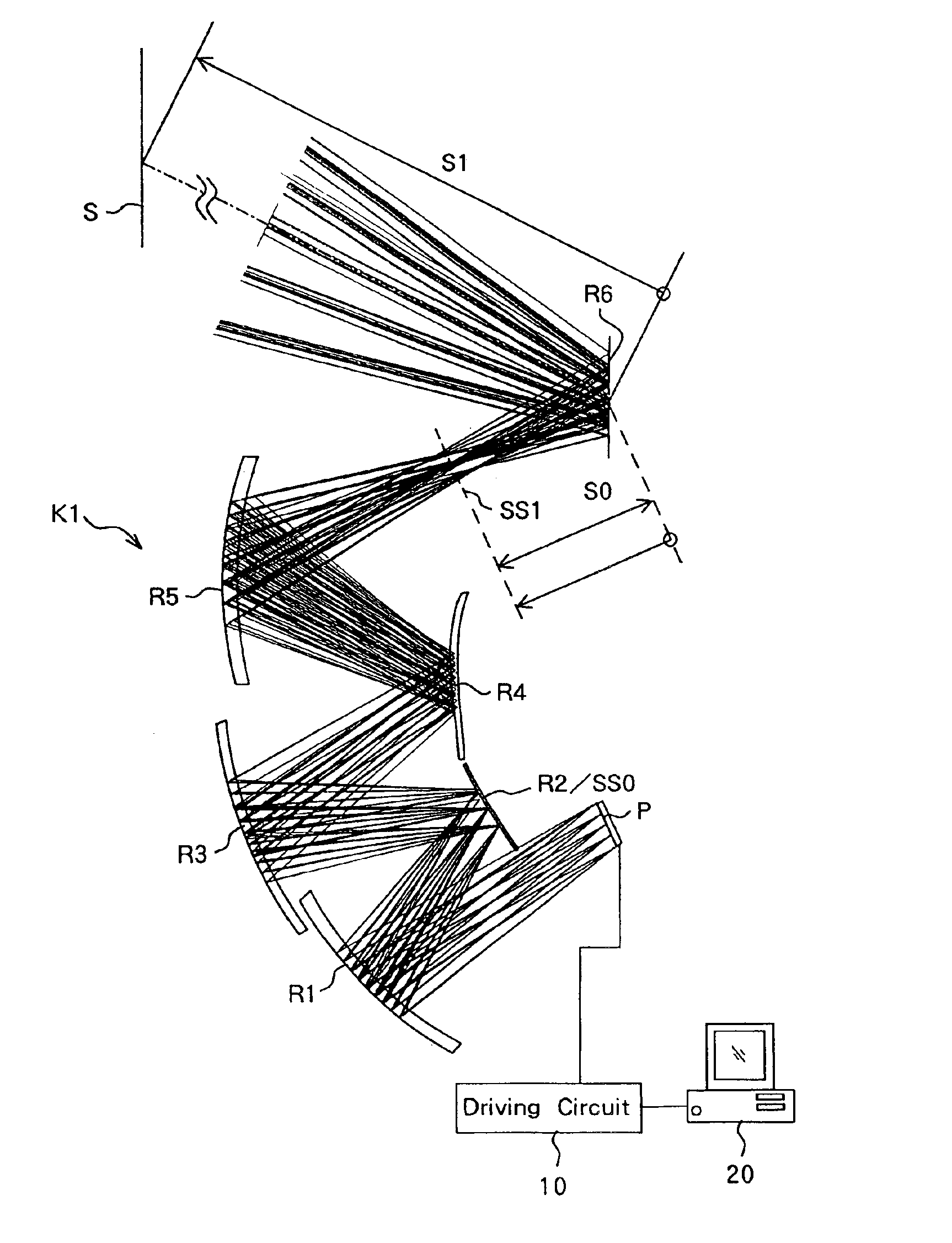
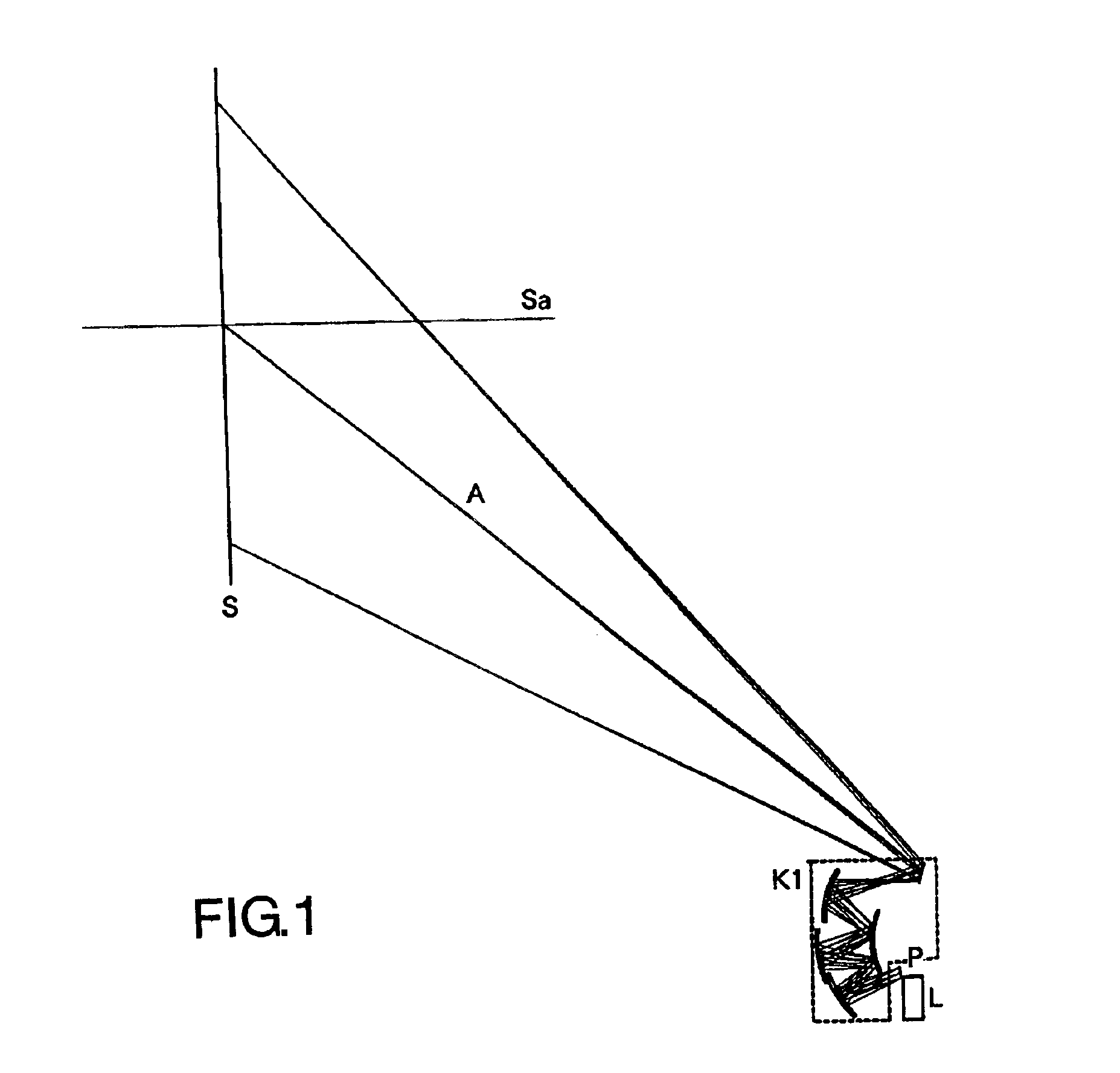
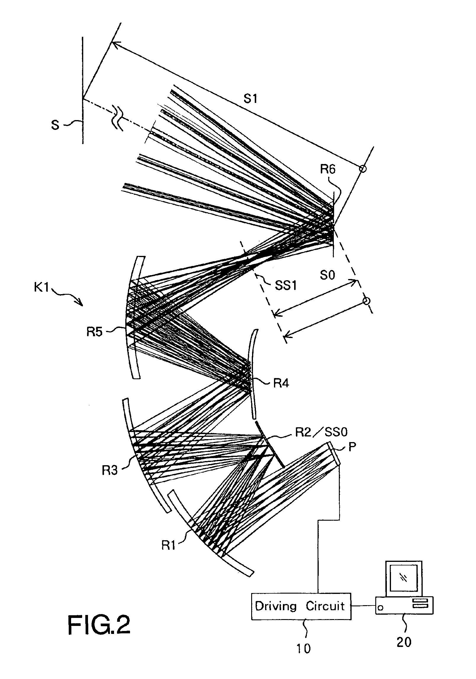
[0060]FIG. 1 is a schematic diagram showing main portions of all optical systems of a projector (a projection type image display apparatus) which employs a projection optical system serving as Embodiment 1 of the present invention. FIG. 2 is an enlarged view of the projection optical system.

[0061]In FIGS. 1 and 2, P shows an image forming element for which a reflective type dot matrix liquid crystal display, a digital micromirror device or the like can be used.

[0062]A driver circuit 10 is connected to the image forming element P as shown in FIG. 2. The driving circuit 10 is provided with image information from an image information supply apparatus 20 such as a personal computer, a VCR, a television, a DVD player, a cellular phone, a radio wave receiver (wired or wireless) or the like. The driving circuit 10 drives the image forming element P such that an original image corresponding to the input image information is displayed on the image forming element P. In th...

embodiment 2

[0080](Embodiment 2)

[0081]FIG. 5 is a schematic diagram showing main portions of all optical systems of a projector employing a projection optical system which is Embodiment 2 of the present invention. FIG. 6 is an enlarged view of the projection optical system.

[0082]In FIGS. 5 and 6, P shows an image forming element for which a reflective type dot matrix liquid crystal display, a digital micromirror device or the like can be used.

[0083]L shows an illumination optical system which illuminates the image forming element P. The illumination system L is formed of a lamp, a condenser lens, a filter for selecting a wavelength or the like.

[0084]K shows the projection optical system which guides light modulated by the image forming element P to a screen S and forms an image on the screen S. The projection optical system K is formed of a refractive optical system K2 which includes a plurality of off-axial refractive lenses and a reflective optical system K3 which employs the off-axial optica...


PUM


Abstract

A projection optical system which has a short projection distance and a compact structure, and allows oblique projection. The projection optical system projects luminous flux from an image forming element for forming an original image onto a projection surface which is oblique to a central principal ray which is a principal ray of luminous flux traveling from the center of the original image to the center of a finally formed image. The system includes a plurality of reflecting surfaces each having a curvature. In addition, the projection optical system satisfies a predetermined expression (1).

Description

BACKGROUND OF THE INVENTION[0001]1. Field of the Invention[0002]The present invention relates to a projection optical system for use in a projection type image display apparatus such as a projector.[0003]2. Description of the Related Art[0004]Conventionally, various passive-type projectors have been proposed in which an image forming element such as a liquid crystal display panel is illuminated with luminous flux from a light source and modulates the luminous flux into transmitted light or reflected light for displaying an image before the light is enlargingly projected onto a projection surface such as a screen by a projection optical system.[0005]Some of the projection optical systems for use in such projectors allow projection in a direction which is oblique (diagonal) to the screen (hereinafter referred to as “oblique projection”) in order to achieve a larger size of a projected image and a smaller thickness of the apparatus at the same time.[0006]For example, Japanese Patent Ap...

Claims


Application Information

Patent Timeline
Patent Type & Authority Patents(United States)
IPC IPC(8): G02B17/06G02B17/00G02B17/08G03B21/00H04N5/74G02B13/18G02B27/18G03B21/14
CPCG02B17/0663G02B17/0816G02B17/0848G02B17/0852G03B21/00H04N5/74G03B21/005
Inventor CHATANI, SAWAKOKUREMATSU, KATSUMIISHII, TAKAYUKISUNAGA, TOSHIHIROKURIOKA, YOSHIAKI
Owner CANON KK
Why Eureka
Try Eureka