Connection cap and wire connection method using same

a technology of connection cap and wire connection, which is applied in the direction of connection end cap, cable junction, coupling device connection, etc., can solve the problems of high cost, low yield, and high time requirements, and achieve the effect of reducing the number of process steps, shortening the processing time, and improving the efficiency of wire-connecting operation

Inactive Publication Date: 2005-10-04
YAZAKI CORP
View PDF7 Cites 27 Cited by
  • Summary
  • Abstract
  • Description
  • Claims
  • Application Information

AI Technical Summary

Benefits of technology

[0013]In view of the above points, it is an object of this invention to provide a connection cap, as well as a wire connection method using it, in which by effecting the connection of conductors of wires, an insulating / waterproofing treatment for the conductors and a treatment of water-stop between the wires (sheaths) simultaneously, the number of the process steps is reduced, and the processing time is shortened, so that the efficiency of the wire-connecting operation can be enhanced, and the insulating performance of the conductors can be maintained and secured, and the highly-reliable electrical performance can be obtained.

Problems solved by technology

The wire-connecting operation was carried out via many steps, and therefore there were encountered problems that much time was required and that the cost was high.
Furthermore, when the gap between the wires 59, inserted in the connection cap 50, and the connection cap 50 was large, it took much time for the uncured resin to be cured, and a yield decrease is encountered in the curing treatment step, and besides there was a fear that after the curing of the resin, the wires 59 within the connection cap 50 were moved by an accidental external force, so that cracks or the like developed in the seal layer 56, thus adversely affecting the waterproof ability, and water or the like intruded into the connection cap 50.

Method used


Image

  • Connection cap and wire connection method using same
  • Connection cap and wire connection method using same
  • Connection cap and wire connection method using same

Examples


Embodiment Construction

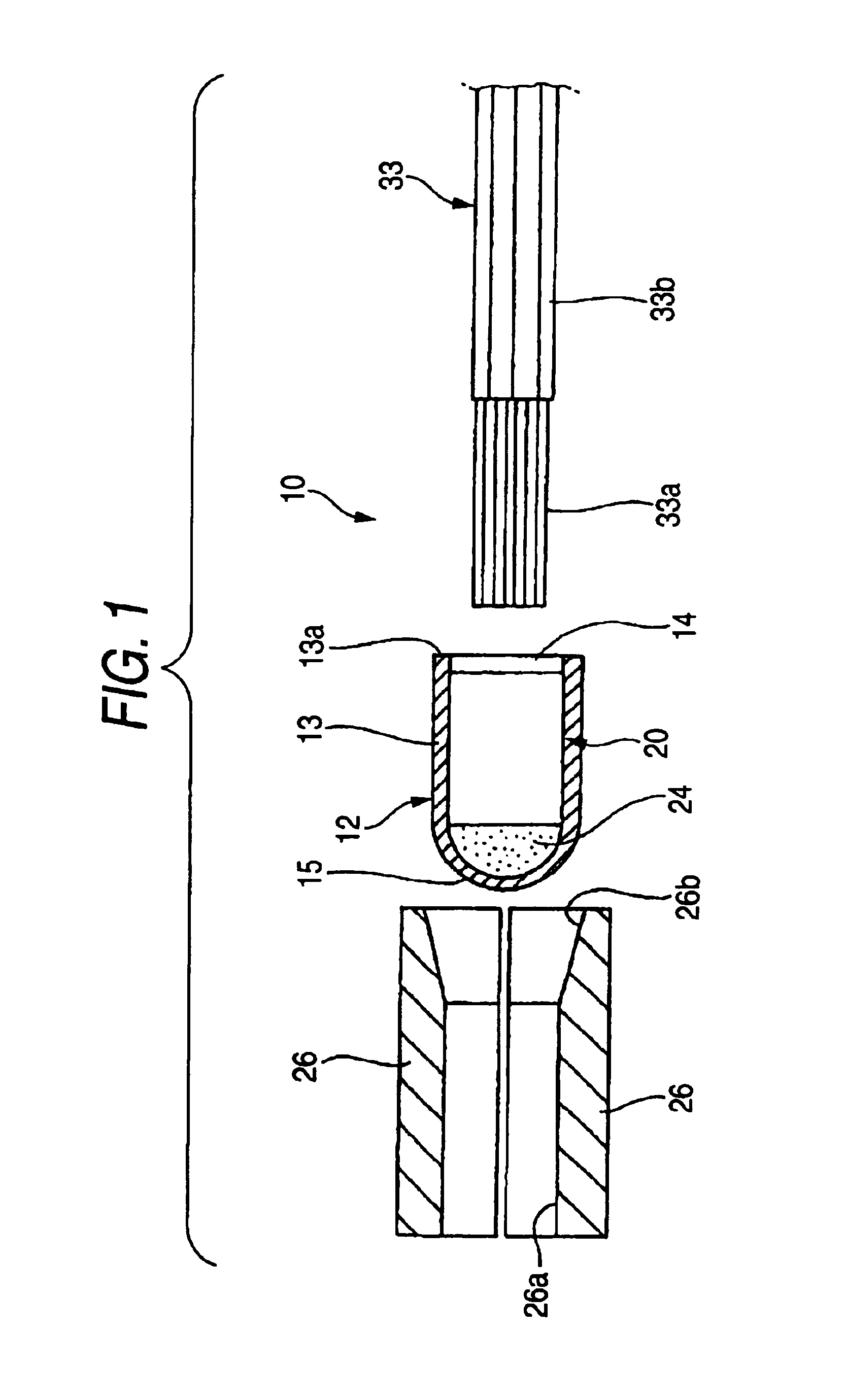
[0037]A specific example of an embodiment according to the present invention will now be described in detail with reference to the drawings.

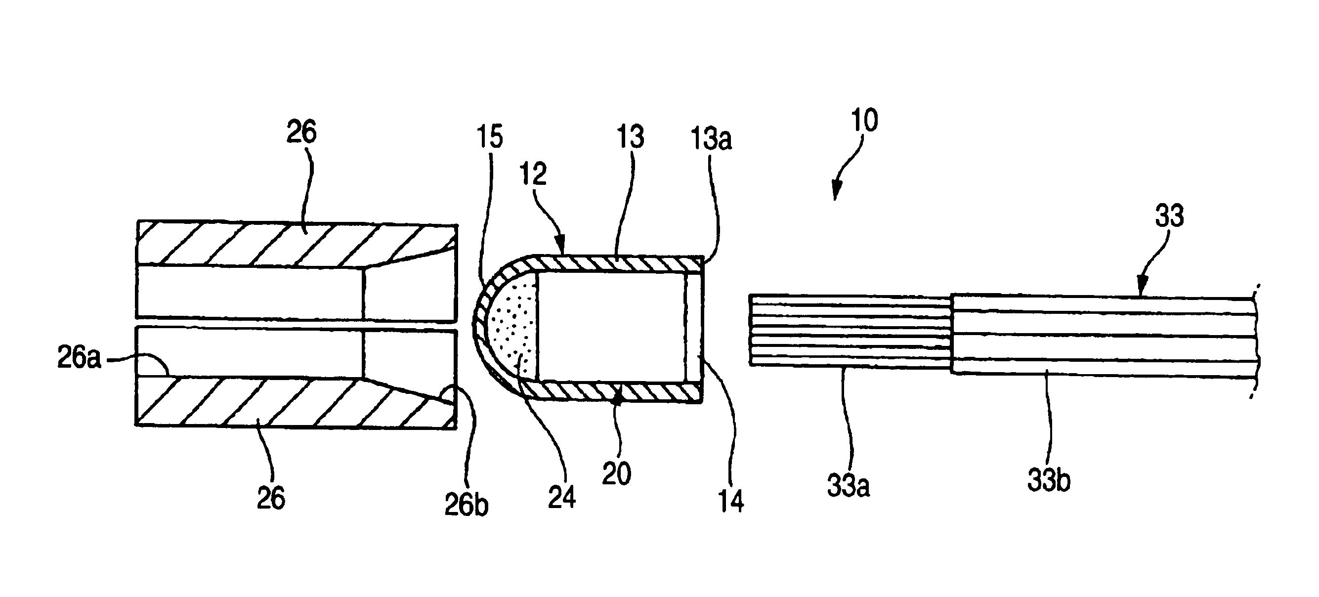
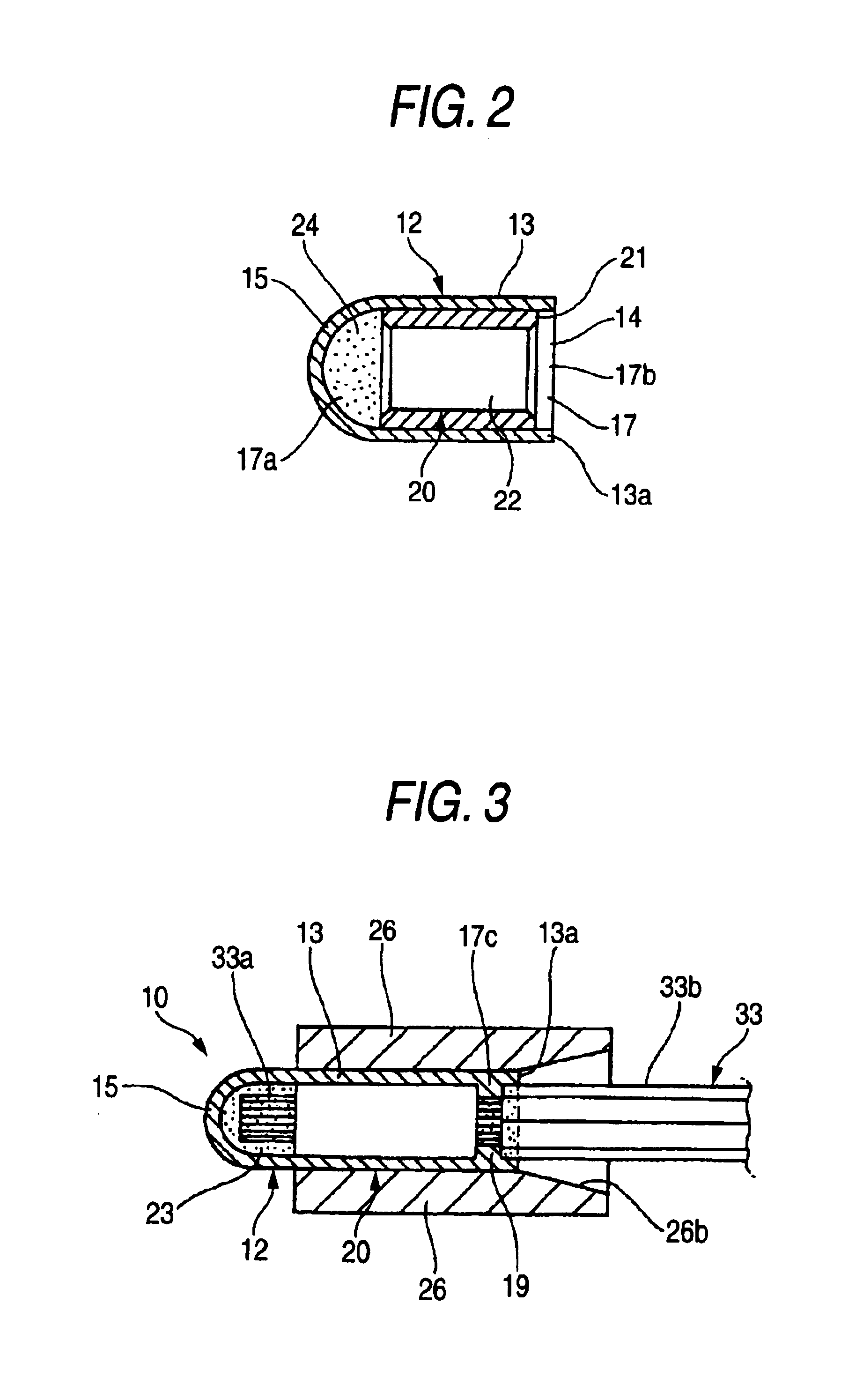
[0038]In one embodiment of the present invention of FIGS. 1 to 5, a connection cap 10 is a connection part which joint-connects conductors 33a of a wire 33 extending from circuit elements (forming an electric circuit) or the like, and insulates and protects the conductors 33a. The wire 33 to be connected are, for example, wire extending from a plurality of actuators such as a motor and a solenoid, branch wire branching off from a main wire portion of a wire harness, wire connected to electronic parts to be received within an electric connection box, wire connected to a battery or the like, and so on. The number of the wire to be connected increases or decreases according to the form of circuit, and in this embodiment the conductors 33a of seven wire 33 are joint-connected together by the connection cap 10.

[0039]A sheath 33b is removed from an en...


PUM


Abstract

A connection cap includes: an insulative cap body for receiving conductors of a wire provided with a back wall and an opening at respective opposite ends thereof; an electrically-conductive conductor connection member which is provided within the cap body and is adapted to be connected to the conductors when the cap body is compressed radially in a state the conductors are received in the cap body; and an electrically-conductive resin material which is filled in a back wall-side portion of the cap body, and is extruded toward the opening to penetrate into interstices between the conductors when the cap body is compressed.

Description

BACKGROUND OF THE INVENTION[0001]This invention relates to a connection cap for insulating and protecting conductors of a wire from the exterior and for joint-connecting the conductors of the wires together, and also relates to a wire connection method using this connection cap.[0002]As one example of related connection caps of this kind as well as one example of wire connection methods using it, there is known one which has been proposed by the Applicant of the present application, and is shown in FIG. 7 (For example, Patent Literature 1).[0003]This related example provides the connection cap 50 excellent in connecting-operation efficiency and waterproofness, and also provides the wire connection method using it. The connection cap 50 comprises a cap body 51 for the insertion of distal end portions of a plurality of wires 59 thereinto, and an insulative seal layer 56 which is filled in the cap body 51, and penetrates into a gap between conductors 59a and the cap body 51 and also in...

Claims


Application Information

Patent Timeline
Patent Type & Authority Patents(United States)
IPC IPC(8): H01R4/20H01R4/10H01R4/22H02G1/14H02G15/08
CPCH01R4/20H01R13/52
Inventor SAKAGUCHI, TADAHISAONUMA, MASANORI
Owner YAZAKI CORP
Why Eureka
Try Eureka