Two-stage converter using low permeability magnetics

a magnetic and low-permeability technology, applied in the direction of electric variable regulation, process and machine control, instruments, etc., can solve the problems of high parts count, thermal derating, oversized magnetics, etc., and achieve the effect of high power factor

Inactive Publication Date: 2005-10-04
SATURN ELECTRONICS & ENG
View PDF53 Cites 122 Cited by
  • Summary
  • Abstract
  • Description
  • Claims
  • Application Information

AI Technical Summary

Benefits of technology

[0020]Another aspect of the present invention is to provide a high power factor to the AC line.
[0021]Another aspect of the present invention is to provide protection from high voltage (input line) transients.

Problems solved by technology

The push-pull approach makes efficient use of the magnetic element by producing AC bias, but suffers from high parts count, thermal derating, oversized magnetics, and elaborate core reset schemes.
In addition to the aforementioned issues the forward converter suffers from inefficient (dc bias) use of the magnetic element.
The magnetics of the prior art power supplies are generally designed for twice the required power rating and require complex methods to reset and cool the magnetic elements resulting in increased installed costs, size, complexity and limited operating temperatures.
This is because high permeability magnetic elements saturate during operation producing heat in the core, which increases permeability and lowers the saturation threshold.
This produces runaway heating, current spikes and / or large leakage currents in the air gap, reduced efficiency, and ultimately less power at higher temperatures and / or high load.
The overall effects are, lower efficiency, lower power density, and forced air / heatsink dependant supplies that require over-rated ferrite magnetic elements for a given output over time, temperature, and loading.

Method used


Image

  • Two-stage converter using low permeability magnetics
  • Two-stage converter using low permeability magnetics
  • Two-stage converter using low permeability magnetics

Examples


Embodiment Construction

[0124]In this and other descriptions contained herein, the following symbols shall have the meanings attributed to them: “+” shall indicate a series connection, such as resistor A in series with resistor B shown as “A+B”. “∥” Shall indicate a parallel connection, such as resistor A in parallel with resistor B shown as “A∥B”.

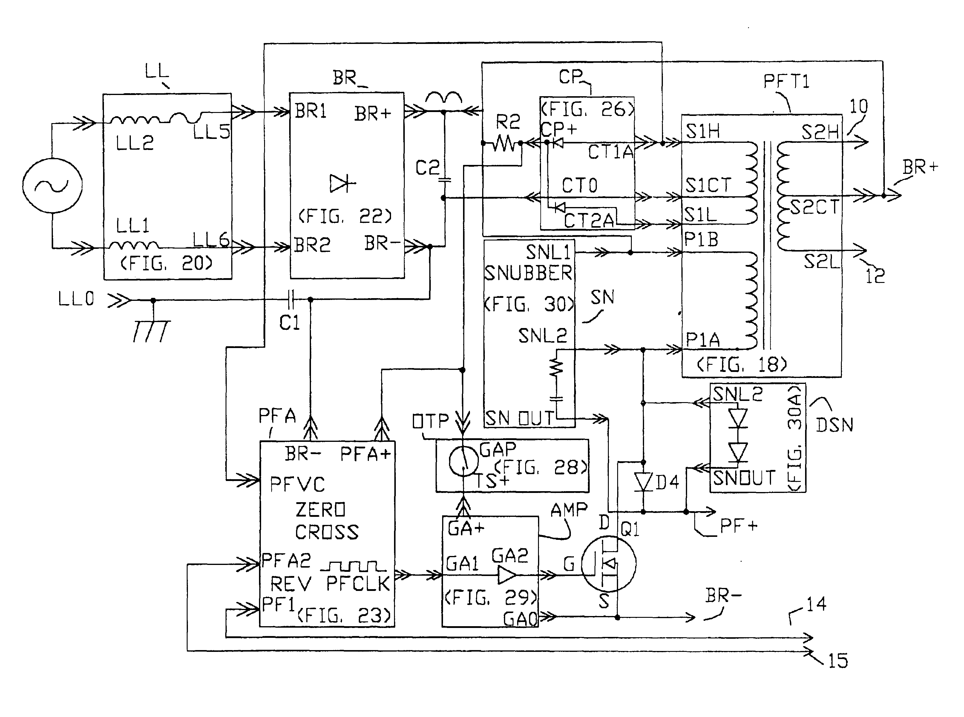
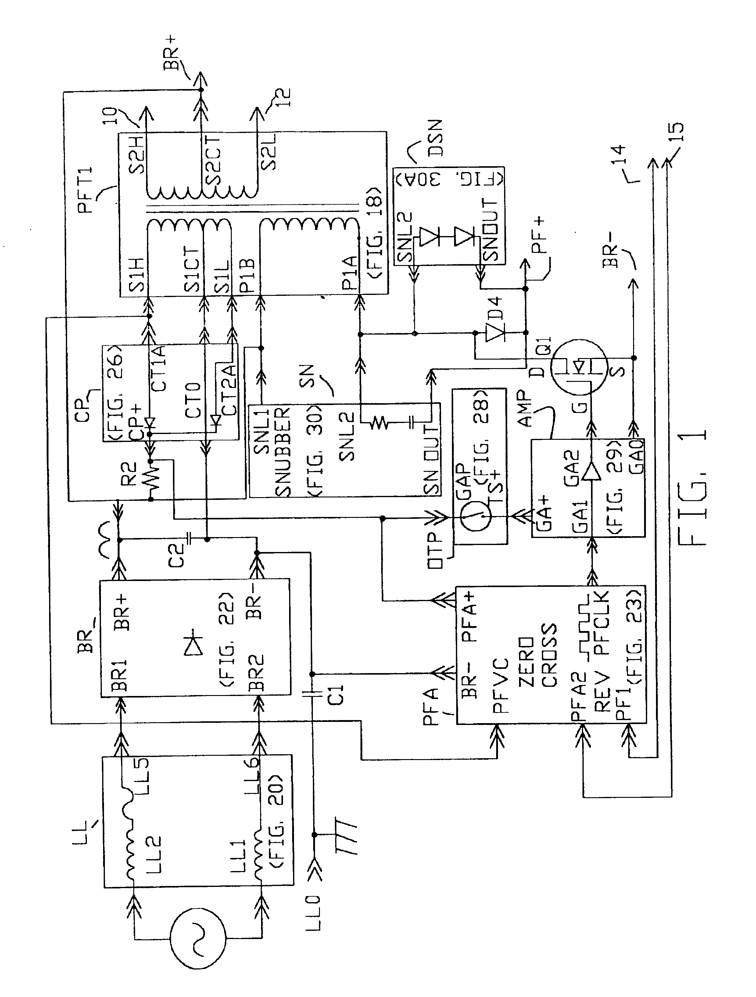
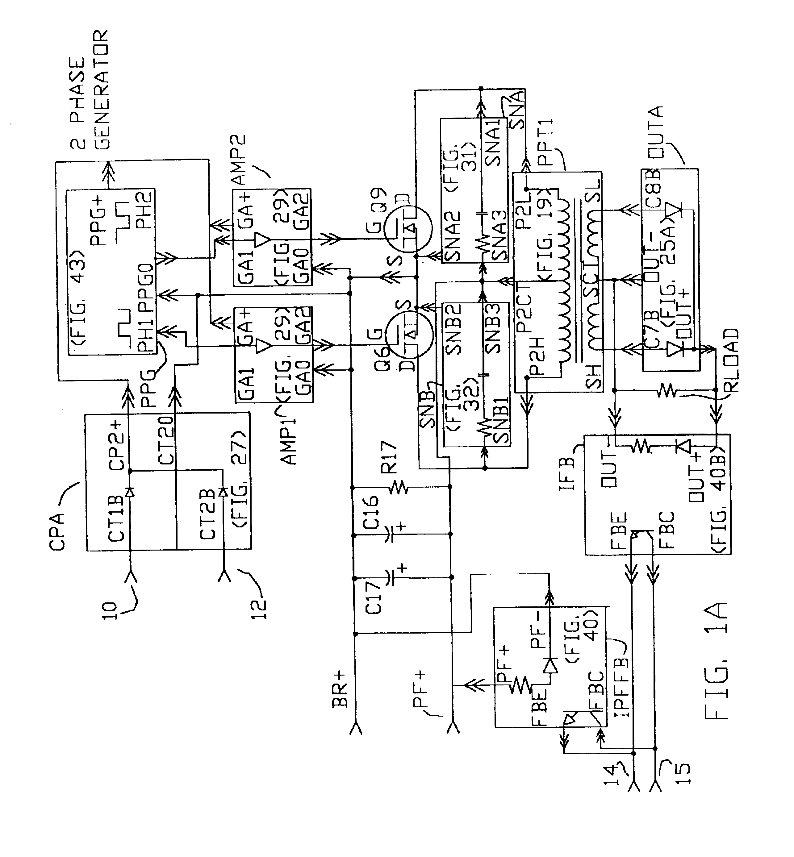
[0125]FIGS. 55 and 55A is a schematic diagram of the preferred two stage power factor corrected AC to DC converter. The invention is comprised of line protection filter sub-circuit LFB (FIG. 62) and ac line monitor sub-circuit ACOKC (FIG. 60). A power factor corrected regulated boost stage with sub-circuits PFC (FIG. 63), snubber sub-circuit SCIN (FIG. 67), snubber sub-circuit SNBB (FIG. 30B), magnetic element sub-circuit PFT2 (FIG. 61), Bias supply sub-circuit CP3 (FIG. 65), buffer sub-circuit AMP (FIG. 29), AC inrush limit sub-circuit ACIR (FIG. 59), voltage feedback sub-circuit VFBI (FIG. 68). Filter capacitor C1, PFC capacitor C2, flyback diode D4, switch tra...


PUM


Abstract

The use of low permeability magnetic material (NSME) with the disclosed design strategies form a two-stage isolated output converter system with the distinct advantages of superior density, efficiency, thermal operating bandwidth, service life, transient survival, and form factor flexibility over the prior art. These improvements are realized by, optimized application of NSME, efficient rectifying flyback management techniques, inclusion of switching buffers that substantially reduce switching losses. The instant invention provides power factor correction, output regulation, inrush limiting, over voltage, over current, over temperature, and transient protection, multi-converter load sharing, hot swapability, and fault signals.
The disclosed system is designed, specified, and certified to function from −40 deg. C. to +65 deg. C. from a 180 vac to 264 vac 50/60 Hz input line and supports 1000 watts of output or 600 watts from 90 vac to 120 vac 50/60 Hz line input at greater then 0.95 power factor and features a packaged power density of 14 watts per cu. in. at high line.

Description

CROSS REFERENCE APPLICATION[0001]This application incorporates by reference U.S. Pat. No. 6,272,025 issued Aug. 7, 2001.FIELD OF INVENTION[0002]The present invention relates to high wattage multi stage isolated output AC / DC power factor corrected converters and power supplies utilizing electrical, mechanical, and packaging design innovations that compliment the use of individual or distributed NSME resulting in efficient operation, high wattage density, rugged transient protection, no thermal derating, fan-less thermal transfer, and long service life.BACKGROUND OF THE INVENTION[0003]There are several basic single or combination topologies commonly used to implement switching converters.[0004]One of the topologies is the push-pull converter. The output signal is derived from the output of an IC network that switches the transistors alternately “on” and “off”.[0005]High frequency square waves on the transistor output drive the magnetic element into AC (alternating current) bias. The i...

Claims


Application Information

Patent Timeline
Patent Type & Authority Patents(United States)
IPC IPC(8): H02M1/00H02M3/00H02M1/42
CPCH02M1/4225H02M1/4258H02M3/00Y02B70/126Y02B70/10
Inventor RIGGIO, CHRISTOPHER ALLENBUSKE, JEFFREY MICHAELTHOMPSON, DAVID R.STAHLE, LYLE J.HUNTER, NATHAN J.WOODLAND, GARTH BLAIR
Owner SATURN ELECTRONICS & ENG
Why Eureka
Try Eureka