
Method to determine a channel characteristic, and discrete wavelet transmitter and receiver to perform the method

a channel characteristic and channel technology, applied in the field of method to determine channel characteristic, and discrete wavelet transmitter and receiver to perform method, can solve the problem of difficult to justify extra expens

Inactive Publication Date: 2005-10-04
RPX CORP
View PDF6 Cites 36 Cited by
  • Summary
  • Abstract
  • Description
  • Claims
  • Application Information

AI Technical Summary

Benefits of technology

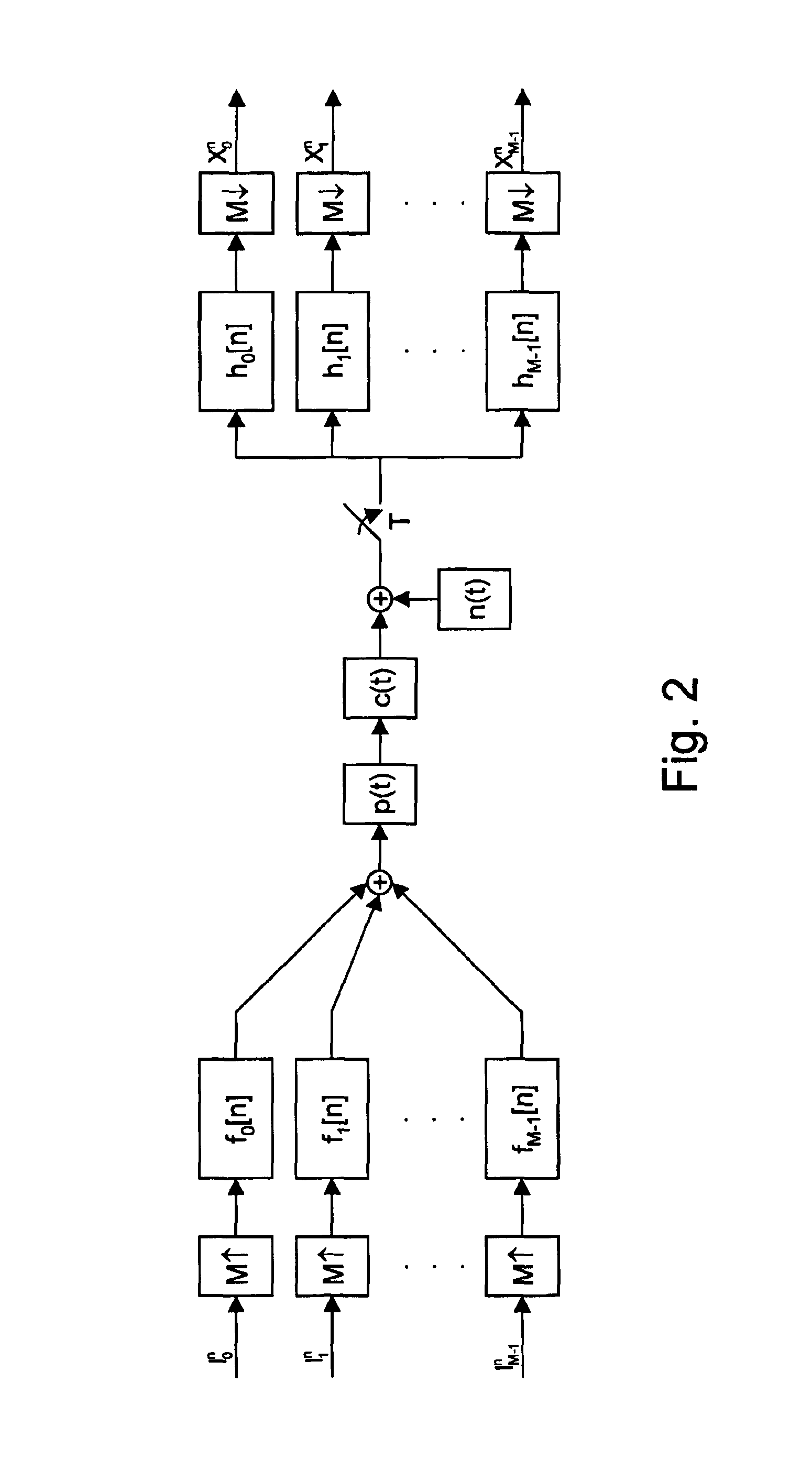
The present invention provides a method to determine the channel characteristic of a loop without needing additional hardware or technicians. This is done by using discrete wavelet multi-tone (DWMT) transmitters and receivers, which combine the pulse amplitude modulated (PAM) symbols generated by the transmitter with the PAM symbols received by the receiver. The method takes advantage of the fact that for a periodic PAM signal, transmitted between a DWMT transmitter and a DWMT receiver, each pair of PAM symbols constitutes a quadrature amplitude modulated (QAM) symbol that is rotated and attenuated by the channel impulse response of the channel over which the signal is transferred. This allows for an automated way to estimate the channel impulse response without needing additional hardware. The method can be performed using the digital signal processing (DSP) functionality typically available in DWMT receivers. Additionally, the patent describes the use of discrete wavelet technology in combination with a periodic PAM signal to estimate the channel impulse response of a loop over which the PAM symbols are transferred. The method also allows for the inverse Fourier transform of the samples of the estimated channel characteristic to obtain a time domain representation of the channel characteristic.

Problems solved by technology

Double-ended testing requires dispatching of a technician, which is an extra expense that is difficult to justify.

Method used


Image

  • Method to determine a channel characteristic, and discrete wavelet transmitter and receiver to perform the method
  • Method to determine a channel characteristic, and discrete wavelet transmitter and receiver to perform the method
  • Method to determine a channel characteristic, and discrete wavelet transmitter and receiver to perform the method

Examples


Embodiment Construction

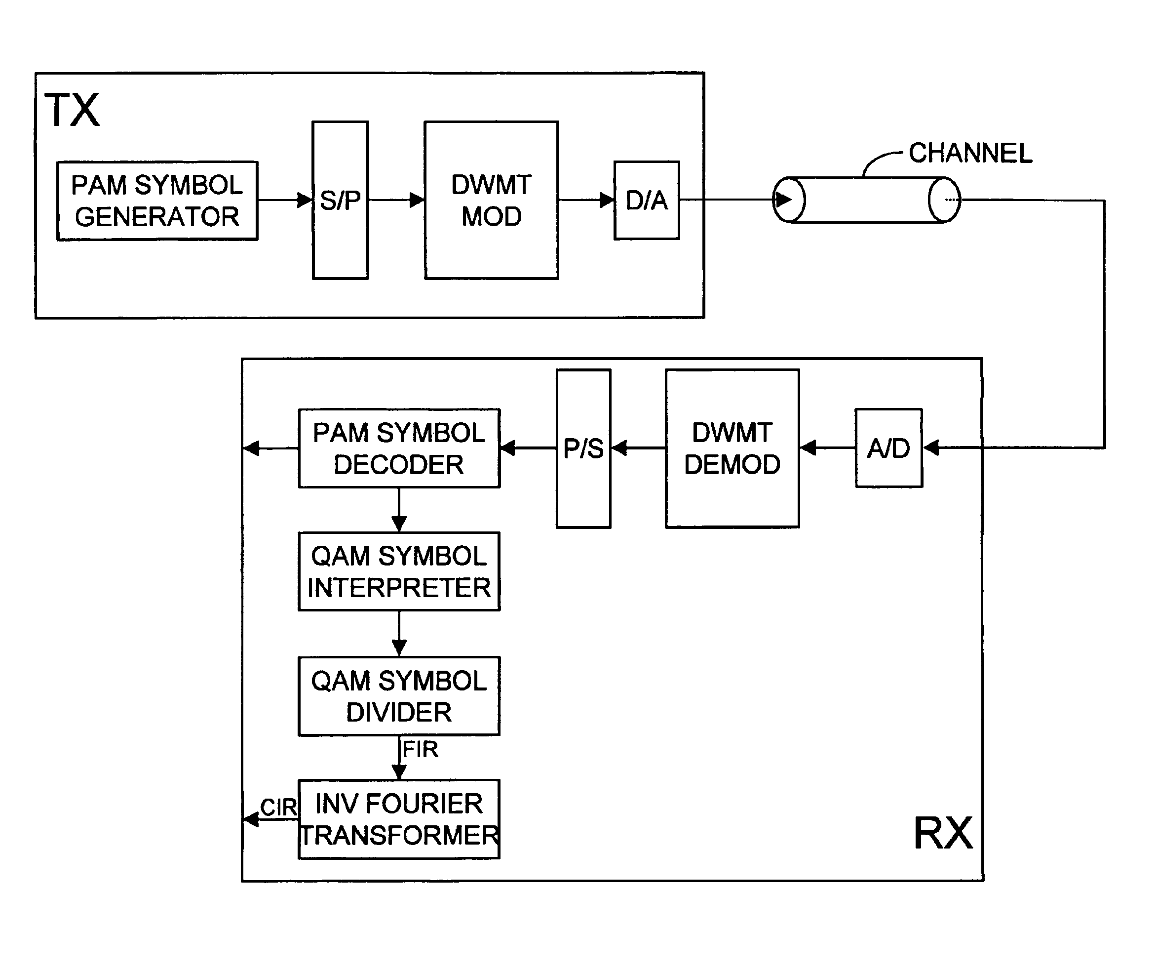
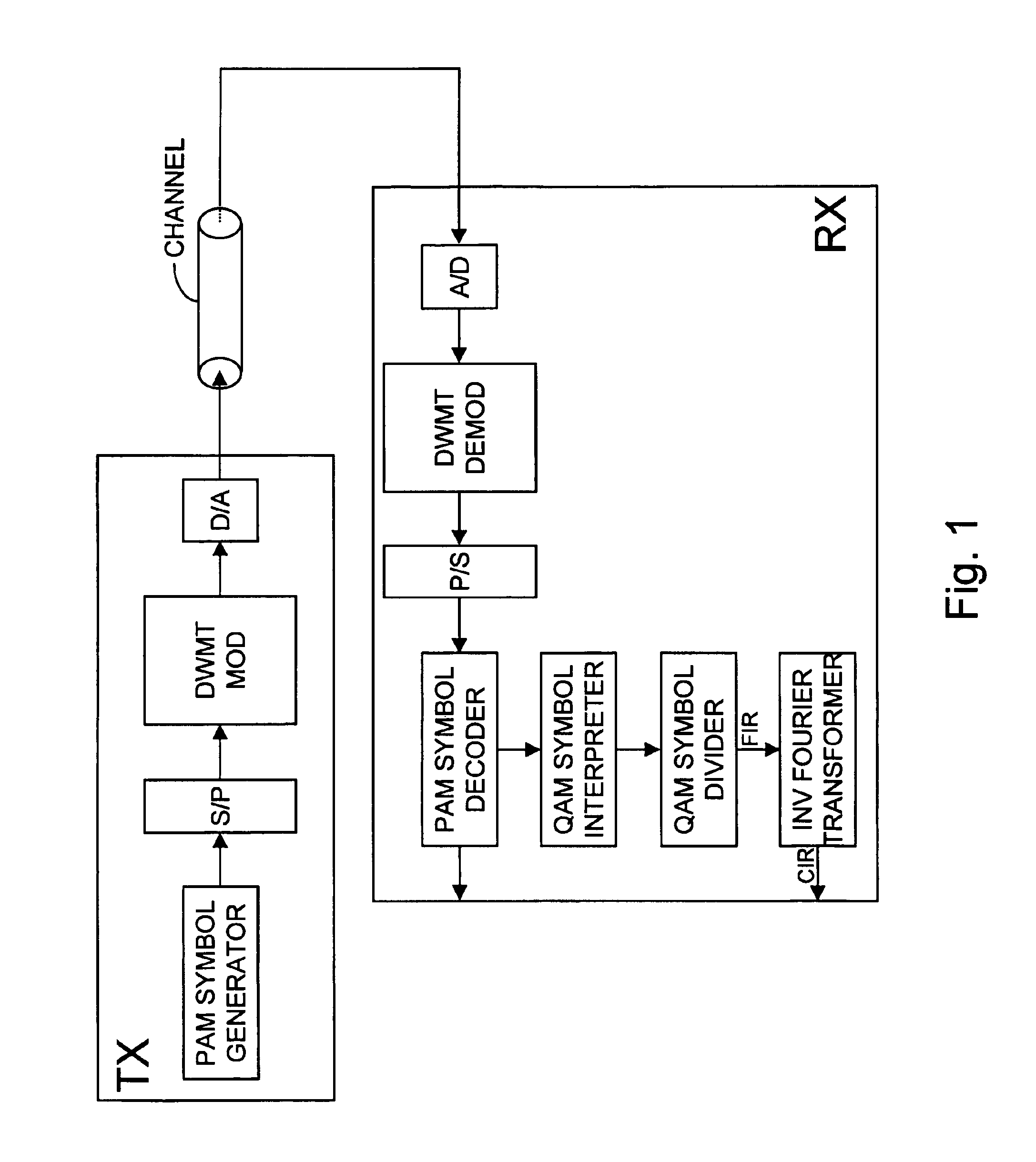
[0015]The discrete wavelet multi tone transmitter TX of FIG. 1 contains the cascade coupling of a pulse amplitude modulation symbol generator PAM SYMBOL GENERATOR, a serial to parallel converter S / P, a discrete wavelet multi tone modulator DWMT MOD, and a digital to analogue converter D / A whose output is coupled to a copper telephone line CHANNEL between the discrete wavelet multi tone transmitter TX and the discrete wavelet multi tone receiver RX. This discrete wavelet multi tone receiver RX contains between an input terminal whereto the copper telephone line CHANNEL is connected and a data output terminal the cascade coupling of an analogue to digital converter A / D, a discrete wavelet multi tone demodulator DWMT DEMOD, a parallel to serial converter P / S and a pulse amplitude modulation symbol decoder PAM SYMBOL DECODER. The latter pulse amplitude modulation symbol decoder PAM SYMBOL DECODER via a second output thereof is connected to the cascade coupling of a quadrature amplitude ...


PUM


Abstract

To determine the channel characteristic of a channel (CHANNEL) between a transmitter (TX) and a receiver (RX), a predetermined periodic signal of pulse amplitude modulated symbols is modulated on waveforms by a cosine modulated filter bank (DWMT MOD) in the transmitter (TX), and the waveforms are transmitted over the channel (CHANNEL). In the receiver (RX), the received pulse amplitude modulated symbols are demodulated from the waveforms by a cosine modulated filter bank (DWMT DEMOD), pairs of the received pulse amplitude modulated symbols are combined to form received quadrature amplitude modulated symbols, and the received quadrature amplitude modulated symbols are divided by the transmitted predetermined pulse amplitude modulated symbols considered pairwise as transmit quadrature amplitude modulated symbols. So, samples of the channel characteristic are generated.

Description

BACKGROUND OF THE INVENTION[0001]The present invention relates to a method to determine samples of an estimated channel characteristic of a channel between a transmitter and a receiver, a discrete wavelet multi tone transmitter comprising a cosine modulated filter bank adapted to modulated waveforms with transmit pulse amplitude modulated symbols, and a discrete wavelet multi tone receiver comprising a cosine modulated filter bank adapted to demodulate received pulse amplitude modulated symbols from waveforms, both equipped to perform steps of this method.[0002]An overview of techniques to test or qualify digital subscriber lines is given in the article ‘DSL Loop Test’ from the authors Eric Hedlund and Tom Cullinan. This article was published on pages 48-52 of the Aug. 24, 1998 issue of the magazineTelephony’, and emphasises the importance of testing loops before xDSL (any Digital Subscriber Line) services are provided there over. Through loop testing line imperfections such as lo...

Claims


Application Information

Patent Timeline
Patent Type & Authority Patents(United States)
IPC IPC(8): H04L25/02H04L27/00H04L27/38H04J11/00H04N7/015
CPCH04L25/0228H04L27/0004H04N7/015
Inventor PEETERS, MIGUEL
Owner RPX CORP
Learn More