Device for reducing power consumption of a monitor and the method thereof

a technology of a monitor and a power consumption reduction, which is applied in the direction of liquid/fluent solid measurement, television system, instruments, etc., can solve the problems of substantial power consumption of approximately 10 w, significant power consumption reduction, and rather slow return time, so as to reduce power consumption and reduce power consumption

Inactive Publication Date: 2005-10-04
IMAGEQUEST
View PDF5 Cites 3 Cited by
  • Summary
  • Abstract
  • Description
  • Claims
  • Application Information

AI Technical Summary

Benefits of technology

[0014]The objectives of the present invention are to provide a device for reducing power consumption of a monitor which has a fast returning time to normal status while its power consumption is less than 5 W, and to provide the method thereof.
[0015]Other objectives of the present invention are to provide a device for reducing power consumption of a monitor operating in a single power-saving mode, and to provide the method thereof.
[0016]In an embodiment, a device for reducing power consumption of a monitor may include a control unit which may generate a power-saving mode signal according to the control signal inputted from an external signal source. The device for reducing power consumption of a monitor may include a first switching unit, coupled to said control unit, which may turn on or off the running power according to said power-saving mode signal, in which said power may be supplied from the power-supply terminal to the deflection drive terminal. The device for reducing power consumption of a monitor may include a second switching unit which may turn on or off the power supplied from the power-supply terminal to the heater, in which said switching unit may operate in the same manner as the first switching unit. The device for reducing power consumption of a monitor may include a voltage-drop unit, coupled to said power-supply terminal and said heater, which may lower the voltage applied from said power-supply terminal to the heater only when said second switching unit is off.
[0021]A method of reducing power consumption may include the following steps of: (1) checking the input status of horizontal and vertical synchronized signals from the external signal source, and generating the power saving mode signal when at least one of said horizontal and vertical synchronized signals is not inputted; (2) shutting off power applied to the deflection drive terminal and to the heater if a power saving mode signal is applied thereto; (3) lowering the voltage of the power applied to the heater and (4) checking the input status of said horizontal and vertical synchronized signals, and discontinuing the generation of said power saving mode signal if all of said signals are inputted.

Problems solved by technology

However, there is a disadvantage of significant reduction of power-saving effects since the power is still maintained to the heater.
However, since re-heating is required to return to the normal status, there is a disadvantage of a rather slow returning time.
In other words, in the cases of Power-saving Modes 1 and 2, there is a problem of substantially high power consumption of approximately 10 W although the returning time to the normal status is fast (i.e., approximately three seconds).
In this regard, there is an additional problem in that the designing and manufacturing of a control unit to implement such functions are rather complex.

Method used


Image

  • Device for reducing power consumption of a monitor and the method thereof
  • Device for reducing power consumption of a monitor and the method thereof
  • Device for reducing power consumption of a monitor and the method thereof

Examples


Embodiment Construction

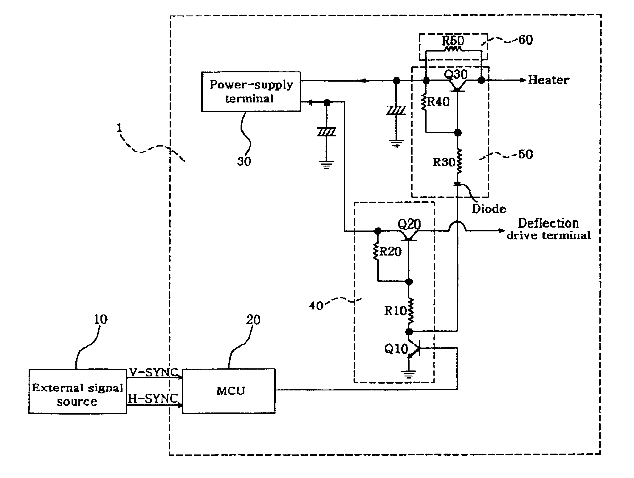
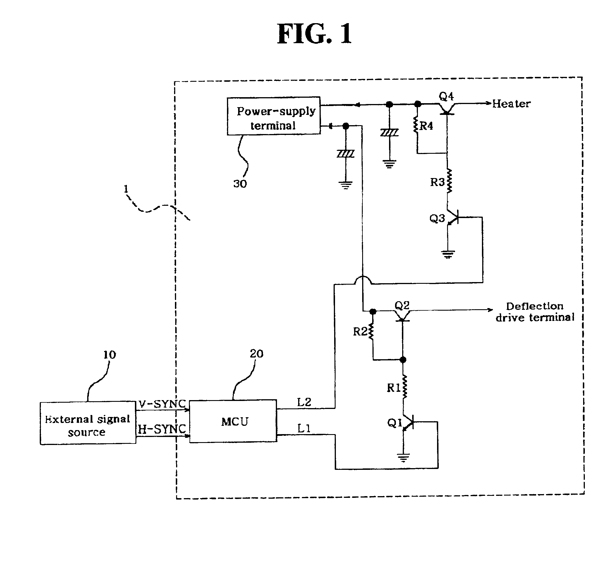
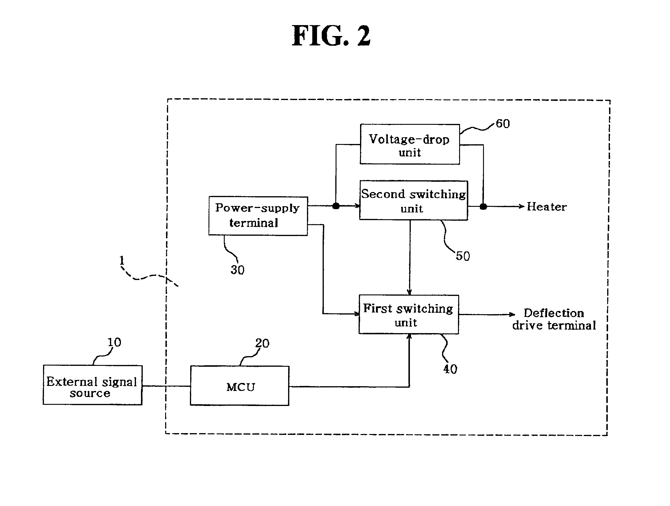
[0025]FIG. 2 is a block diagram illustrating the structure of a device for reducing power consumption of a monitor. As shown in FIG. 2, the device for reducing power consumption of a monitor may include control unit (MCU) 20 which may receive input of control signals from external signal source 10. The device for reducing power consumption may include first switching unit 40 which may be coupled to control unit 20, which may turn on or off the power applied to a deflection drive terminal according to the power-saving mode signal outputted from control unit 20. The device for reducing power consumption may include a second switching unit 50, which may be coupled to first switching unit 40, which may turn on or off the power applied to the heater. The device for reducing power consumption may include voltage-drop unit 60, which may supply power of dropped voltage to said heater when second switching unit 50 is off.

[0026]External signal source 10 may be a device (e.g., a P.C.), which t...


PUM


Abstract

The present invention relates to a device for reducing power consumption of a monitor and the method thereof. The device for reducing power consumption of a monitor according to the present invention comprises a control unit which generates a power-saving mode signal according to the control signal inputted from an external signal source; a first switching unit, connected to said control unit, which turns on or off the power according to said power-saving mode signal, in which said power is supplied from the power-supply terminal to the deflection drive terminal; a second switching unit which turns on or off the power supplied from the power-supply terminal to the heater, in which said switching unit operates in the same manner as the first switching unit; and a voltage-drop unit, connected between said power-supply terminal and said heater, which lowers the voltage applied from said power-supply terminal only when said second switching unit is off, and then supplies the same to said heater. By using a device for reducing power consumption of a monitor and the method thereof according to the present invention, the following effects can be obtained: First, since it operates in a single power-saving mode, it provides a simple construct, which in turn results in enhanced effects in terms of production process and costs. Second, power consumption is reduced to less than 5 W while allowing a fast returning time to normal status.

Description

BACKGROUND OF THE INVENTION[0001]1. Technical Field[0002]The present invention relates to a device for reducing power consumption of a monitor and the method thereof. More particularly, it relates to a device for reducing power consumption of a monitor and the method thereof. Embodiments of the invention have low power consumption and a fast return time to normal operating status while operating in a single mode. Low power consumption and a fast return time are achieved by cutting off the power applied to a deflection drive and a heater according to the control signals inputted from the external signal source, while simultaneously applying a certain amount of dropped voltage to said heater.[0003]2. Background Art[0004]A device for reducing power consumption of a conventional monitor and the method thereof are described as below with references to FIG. 1. FIG. 1 is a schematic which illustrates a conventional device for reducing power consumption of a monitor. In a conventional devic...

Claims


Application Information

Patent Timeline
Patent Type & Authority Patents(United States)
IPC IPC(8): G06F1/32H04N5/68G09G1/00G09G1/04
CPCG06F1/3203G06F1/3265Y02B60/1242Y02D10/00G06F1/32
Inventor KIM, JONG-RINBYUN, YOUNG-KAB
Owner IMAGEQUEST
Why Eureka
Try Eureka