
Automatic electric toothbrush

a technology of electric toothbrushes and brushes, applied in the direction of contact mechanisms, carpet cleaners, cleaning equipments, etc., can solve the problems of toothpaste being shaken off the bristles, affecting the use of the user, and a limited number of users, and achieve the effect of convenient replacemen

Inactive Publication Date: 2005-10-11
FKA DISTRIBUTING CO LLC
View PDF29 Cites 119 Cited by
  • Summary
  • Abstract
  • Description
  • Claims
  • Application Information

AI Technical Summary

Benefits of technology

[0011]Yet another aspect of the invention provides a motorized electric toothbrush that is operable in an automatic mode and has a removable head portion to facilitate replacement when the bristles are worn, and to allow use of the toothbrush by multiple users.
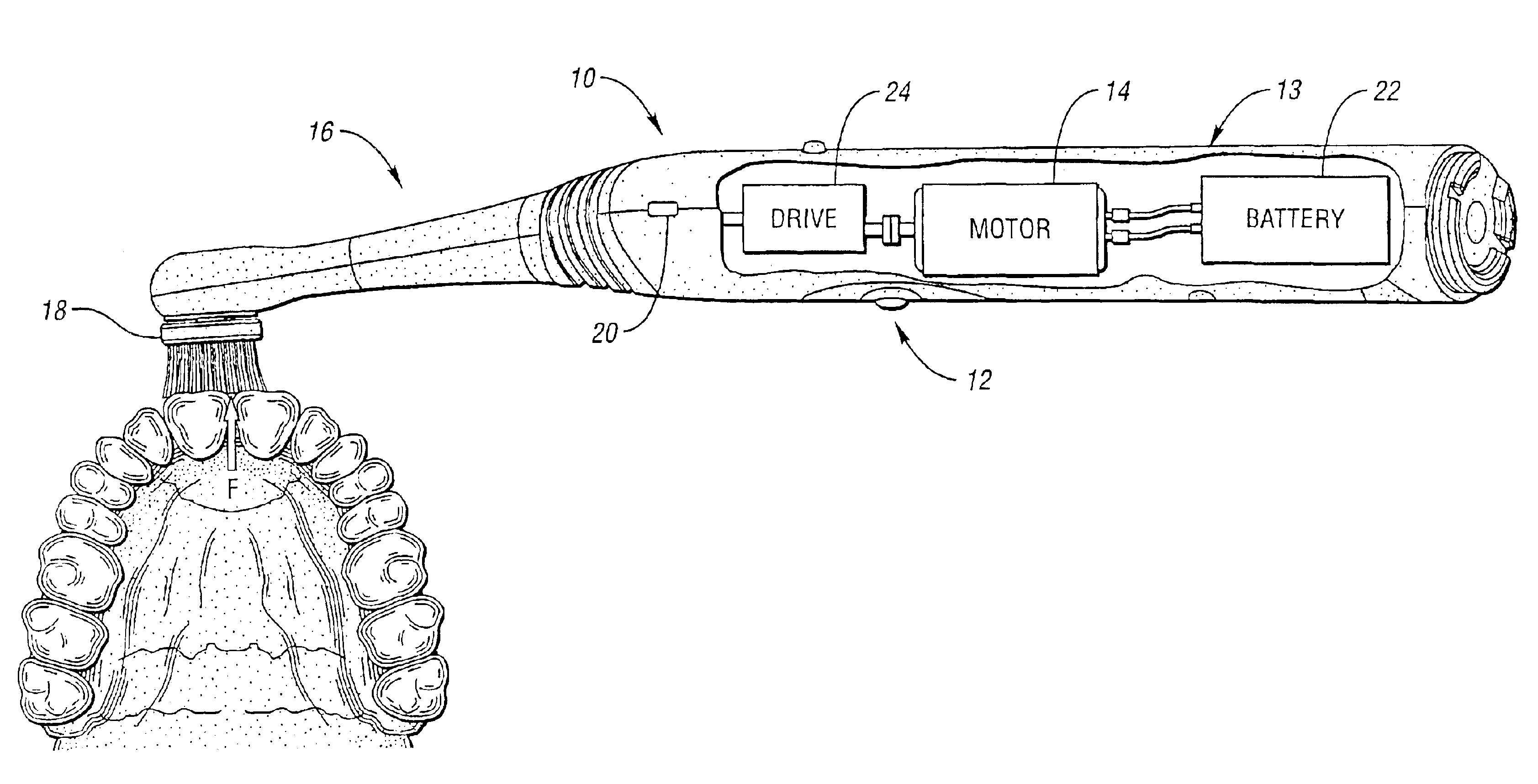
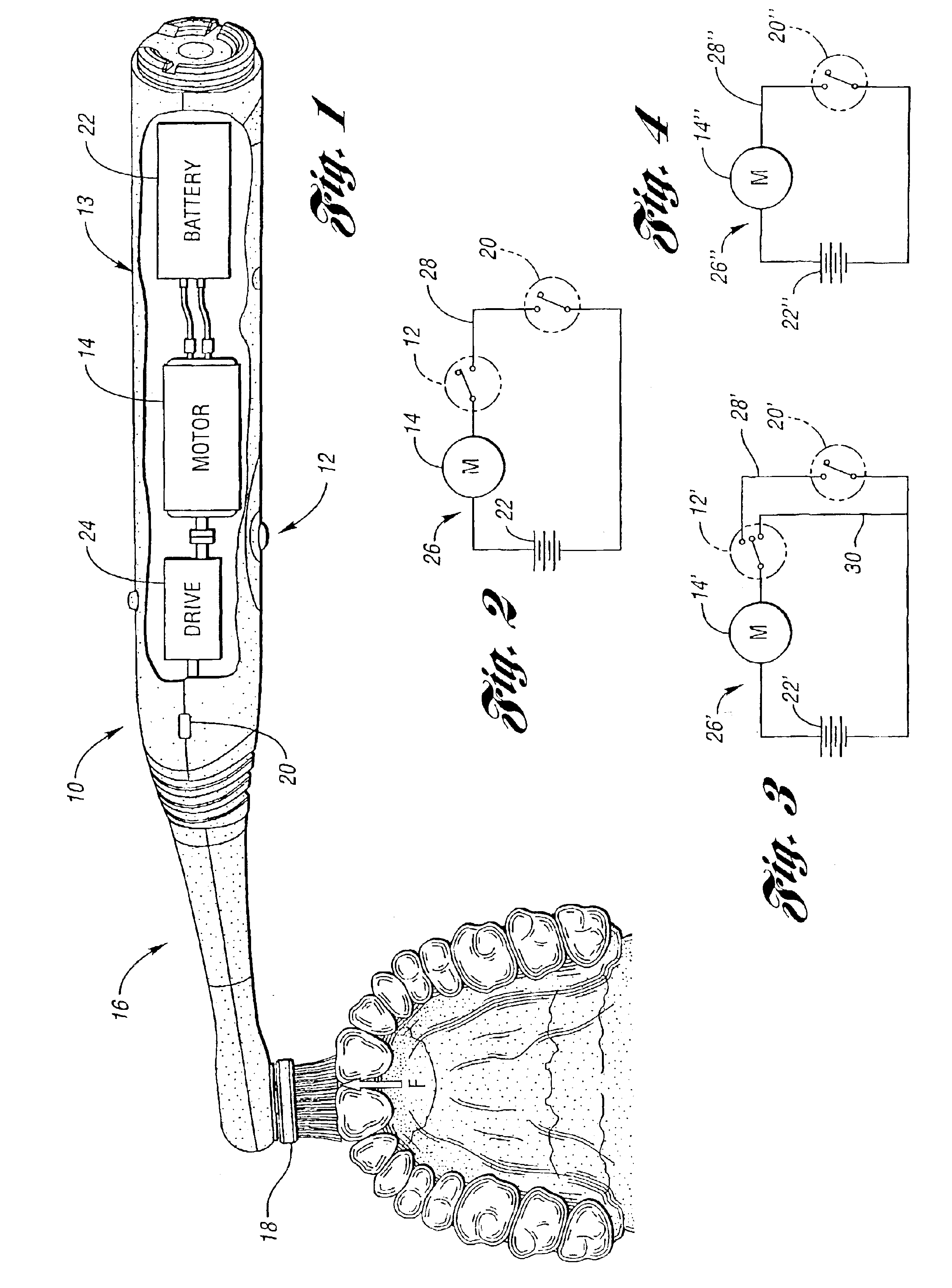
[0012]Accordingly, a motorized electric toothbrush is provided that comprises a handle portion that includes an electric motor. The handle portion is attached to a head portion, which includes a bristle head driven by the motor. A switch is provided for connecting the motor to an electric source. The switch has a first position for preventing motorized operation of the toothbrush, and a second position for effecting motorized operation of the toothbrush. The switch is automatically placed in the second position when the toothbrush is used by an operator.
[0013]Another aspect of the invention provides a motorized electric toothbrush that comprises a handle portion that includes an electric motor. The handle portion is attached to a head portion, which includes a bristle head driven by the motor. A first switch is provided for connecting the motor to an electric source. The first switch has a first position for preventing motorized operation of the toothbrush, and a second position for facilitating automatic operation of the toothbrush. The toothbrush also includes a second switch having a first position for preventing motorized operation of the toothbrush, and a second position for effecting motorized operation of the toothbrush when the first switch is in the second position. The second switch is automatically placed in the second position when the toothbrush is used by an operator.
[0014]A further aspect of the invention provides a motorized electric toothbrush having a handle portion that includes an electric motor. The handle portion is attached to a head portion, which includes a bristle head driven by the motor. A first switch is provided for connecting the motor to an electric source. The first switch has a first position for preventing motorized operation of the toothbrush, a second position for facilitating automatic operation of the toothbrush, and a third position for continuous motorized operation of the toothbrush. A second switch has a first position for preventing motorized operation of the toothbrush, and a second position for effecting motorized operation of the toothbrush when the first switch is in the second position. The second switch is automatically placed in the second position when the toothbrush is used by an operator.
[0015]The above object and other objects, features, and advantages of the present invention are readily apparent from the following detailed description of the best modes for carrying out the invention when taken in connection with the accompanying drawings.

Problems solved by technology

With such a switch, the user has a limited number of choices.
Both of these choices may have undesirable consequences.
When the user engages the motor prior to placing the brush head in the mouth, the rapid movement of brush head may cause the toothpaste to be shaken off the bristles.
Conversely, if the user waits until the brush head is inside the mouth, and in particular in contact with the teeth, it may be difficult to engage the switch, depending on its position relative to the user's hand.
None of these designs includes an automatic mode of operation that provides for motorized operation only when the toothbrush is being used by an operator.

Method used


Image

  • Automatic electric toothbrush
  • Automatic electric toothbrush
  • Automatic electric toothbrush

Examples


first embodiment

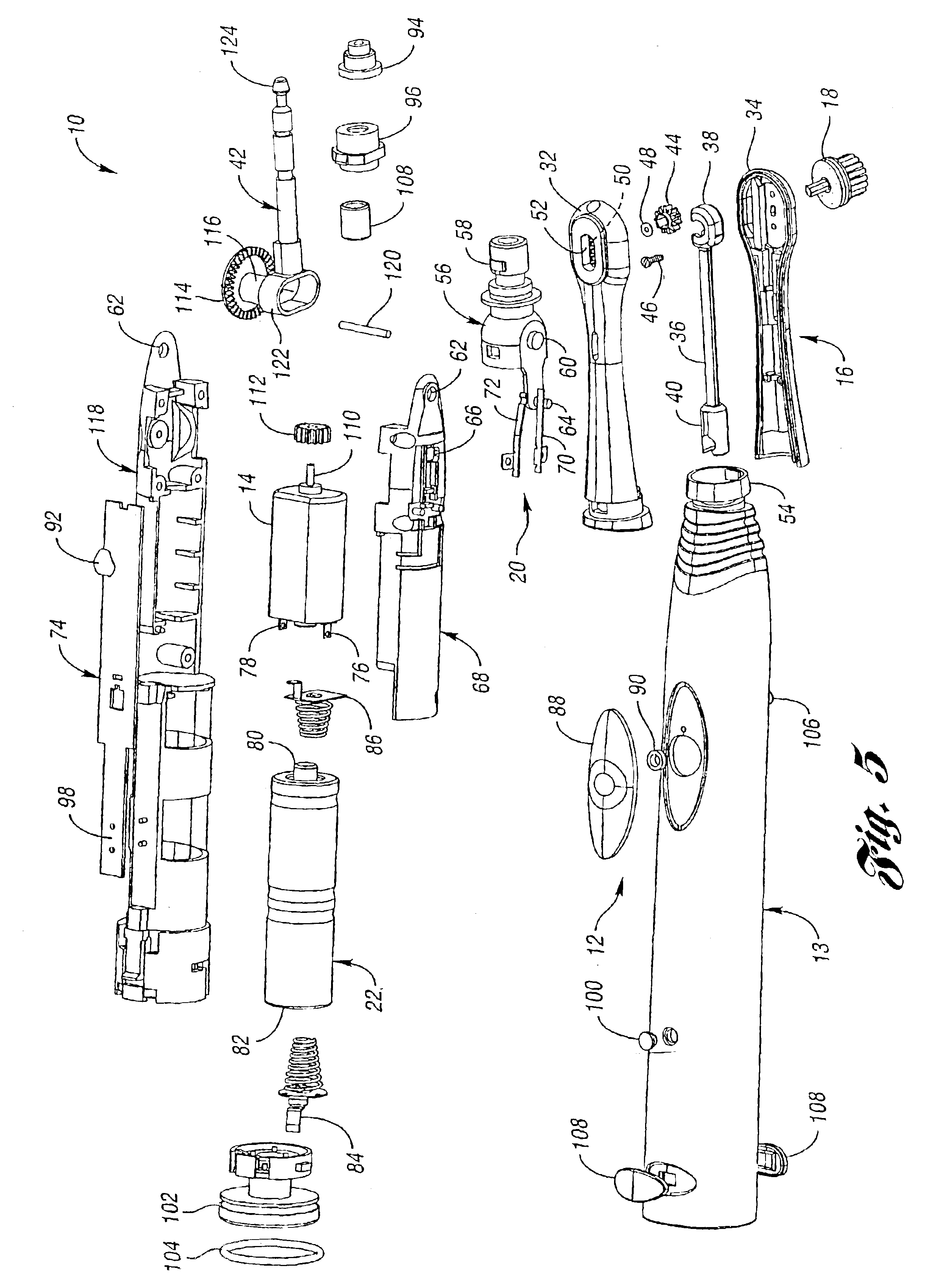
[0055]As in the previous embodiment, the toothbrush 126 includes an automatic mode of operation. To facilitate the automatic mode of operation, the toothbrush 126 has a first switch (not shown) that is configured as in the previous embodiment. A second switch 146, seen in FIGS. 10 and 12, includes a contact plate 148 having legs 150 and a contact rod 152. The contact plate 148 and the contact rod 152 are disposed within the handle portion 128 and are covered by a seal 154. Similar to the contact plates 70, 72 used in the first embodiment, the contact plate 148 and the contact rod 152 are wired to a PC board (not shown).

[0056]The method by which the removable head portion 132 attaches to the handle portion 128 is also different from the first embodiment. An adaptor 156, seen in FIGS. 11 and 12, is located inside the housing 136 of the removable head portion 132, and snaps into recesses 157 in the handle portion 128, (see FIG. 11). This attachment allows the removable head portion 132...

third embodiment

[0059]Portions of the present invention are shown in FIGS. 13 and 14. In this embodiment, a toothbrush 160 includes a handle portion 162 that has a first housing 163, and a removable head portion 164 that has a second housing 165 and a bristle head (not shown). As in the previous embodiments, the toothbrush 160 includes a first switch (not shown) having a first, or “off” position that prevents motorized operation of the toothbrush 160, and a second, or “automatic” position that allows the toothbrush 160 to function in an automatic mode. A second switch 166 comprises first and second stationary contact plates 168, 170, and a third contact plate 172. The removable head portion 164 includes a projection 174 that fits into a notch 176 in the first housing 163 of the handle portion 162.

[0060]The removable head portion 164 attaches to the handle portion 162 at snaps 178. This connection allows the removable head portion 164 be securely attached to the handle portion 162, and at the same t...

fifth embodiment

[0066]FIG. 20 shows a toothbrush 222 in accordance with the present invention. The toothbrush 222 has a handle portion 224 and a removable head portion 226. The handle portion 224 includes a compressible portion 228. Unlike previous embodiments, the toothbrush 222 only has one switch 229 which comprises a magnet 230 and a Hall effect sensor 232. The magnet 230 is located beneath the compressible portion 228, and application of force (F) to the compressible portion 228 causes the distance between the magnet 230 and the Hall effect sensor 232 to decrease. When this distance is small enough, current flows through the Hall effect sensor 232, and the motor (not shown) is engaged.

[0067]FIG. 21 shows a sixth embodiment of the present invention. A toothbrush 234 includes a handle portion 236 and a removable head portion 238. As in the fifth embodiment, the toothbrush 234 includes only one switch 240. The switch 240 comprises first and second contact plates 242, 244 located beneath a compres...


PUM


Abstract

An motorized electric toothbrush (10) includes a removable brush head (16) and a switch (12) that allows the toothbrush (10) to be used in an “automatic” mode. The “automatic” mode provides for intermittent motorized operation, such that when the brush head (16) contacts the operator's teeth, a second switch (20) is automatically actuated and the motor (14) engaged. The brush head (16) is easily removed for replacement when the bristles become worn or allow use of the toothbrush (10) by multiple users.

Description

CROSS-REFERENCE TO RELATED APPLICATION[0001]This application is the U.S. national phase of PCT application number PCT / US02 / 20458, filed Jun. 28, 2002, which further claims the benefit of U.S. provisional application Ser. No. 60 / 302,010, filed Jun. 29, 2001.BACKGROUND OF THE INVENTION[0002]1. Field of the Invention[0003]The present invention relates to a motorized electric toothbrush having an automatic mode of operation.[0004]2. Background Art[0005]Use of motorized electric toothbrushes used as an aid in cleansing teeth is well known. Typically these toothbrushes employ rotating, reciprocating, or oscillating motion, or a combination thereof, to effectuate the cleaning process.[0006]A feature commonly found on these toothbrushes is an on / off switch located on or near the handle portion of the toothbrush. The primary feature of such a switch is that it remains either in the “on” position or the “off” position until the user manually changes it. With such a switch, the user has a limi...

Claims


Application Information

Patent Timeline
Patent Type & Authority Patents(United States)
IPC IPC(8): A61C17/22A61C17/16
CPCA61C17/22A61C17/221A61C17/225A61C17/3436
Inventor LEV, MORDECHAIFERBER, ROMAN S.NEMAZI, JOHN E.
Owner FKA DISTRIBUTING CO LLC
Learn More