Radiation sources and radiation scanning systems with improved uniformity of radiation intensity

a radiation source and radiation scanning technology, applied in the direction of material analysis using wave/particle radiation, instruments, nuclear engineering, etc., can solve the problem of large cargo containers, cross-border smuggling of contraband, etc., and achieve the effect of uniform radiation intensity and improved intensity distribution of radiation beams on the face of objects under inspection

Inactive Publication Date: 2005-10-11
VAREX IMAGING CORP
View PDF24 Cites 65 Cited by
  • Summary
  • Abstract
  • Description
  • Claims
  • Application Information

AI Technical Summary

Benefits of technology

[0009]In accordance with embodiments of the invention, the intensity distribution of a radiation beam on a face of an object under inspection is improved by deflecting a beam of charged particles, such as electrons, along a plurality of central rays to cause impact on a target material to generate radiation beams along the plurality of central rays. The greater the number of beams along respective central rays, the more uniform the radiation intensity on the face of the object. Embodiments are disclosed that effectively deflect the beam of charged particles along a large number of central rays, which may result more uniform radiation intensity on the face of the object.

Problems solved by technology

While the smuggling of contraband onto planes in carry-on bags and in luggage has been a well-known, on-going concern, a less publicized but also serious threat is the smuggling of contraband across borders and by boat in large cargo containers.

Method used


Image

  • Radiation sources and radiation scanning systems with improved uniformity of radiation intensity
  • Radiation sources and radiation scanning systems with improved uniformity of radiation intensity
  • Radiation sources and radiation scanning systems with improved uniformity of radiation intensity

Examples


Embodiment Construction

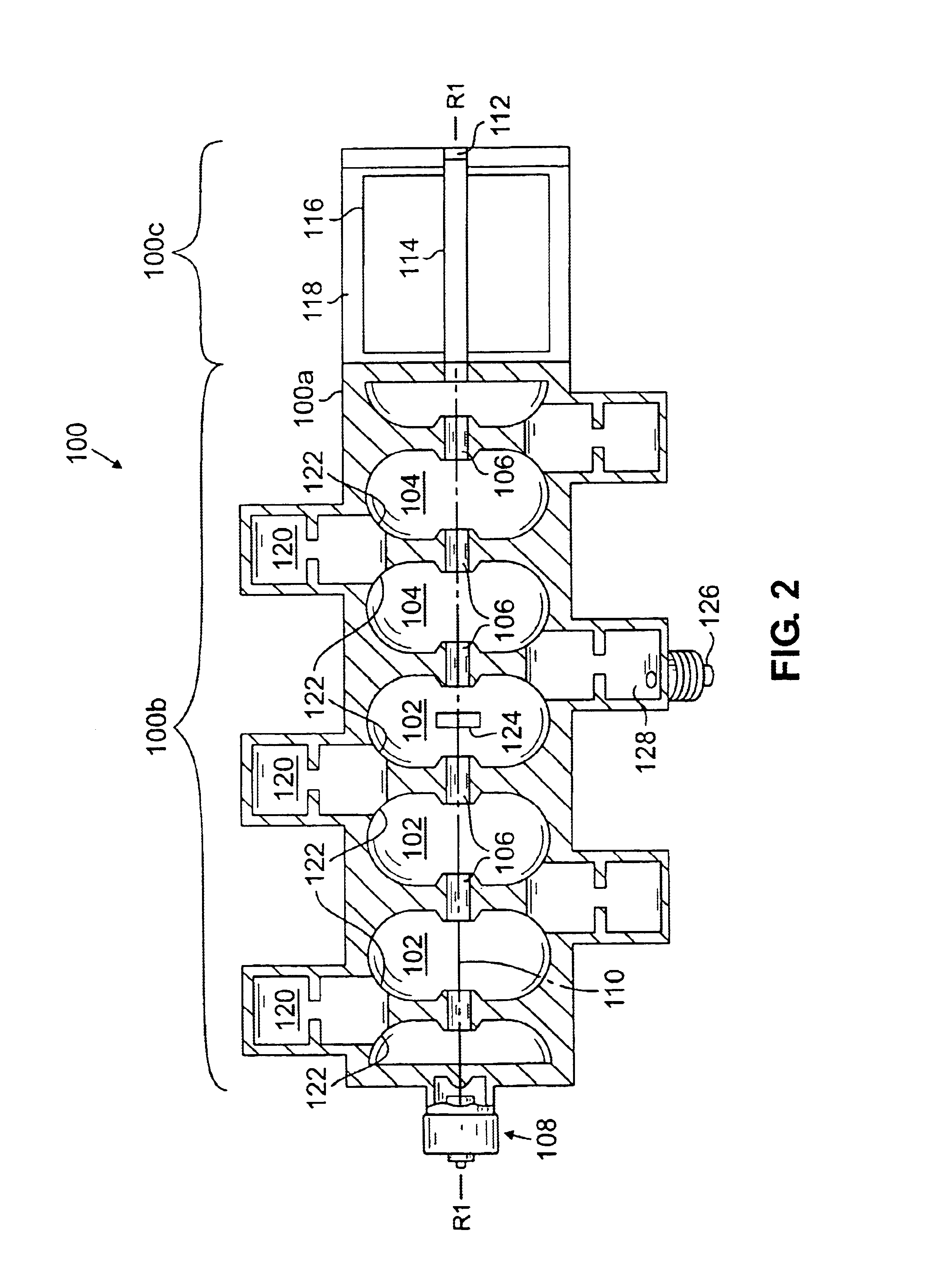
[0037]FIG. 2 is a schematic axial sectional view of an example of a radiation source 100, in accordance with an embodiment of the invention, wherein a beam of charged particles is accelerated and directed towards a target to generate radiation. The charged particles may be electrons or protons. The resulting radiation may be X-ray radiation, gamma ray radiation, or neutrons, for example.

[0038]In one example, the source 100 is an accelerator, such as a linear accelerator, generating X-ray radiation. The linear accelerator 100 may be a charged particle standing wave accelerator, for example. The linear accelerator 100 comprises a housing 100a with a body portion 100b and a distal portion 100c. The body portion 100a includes a chain of electromagnetically coupled, doughnut shaped resonant cavities 102, 104, with aligned central beam apertures 106. An electron gun 108 at one end of the chain of cavities emits an electron beam 110 through the apertures 106. The source 100 may be a betatr...


PUM


Abstract

A radiation source is disclosed comprising a source of charged particles that travel along a path. Target material lies along the path to generate radiation upon impact by the beam. A magnet is provided to deflect the beam prior to impacting the target. The magnet may generate a time-varying magnetic field or a constant magnetic field. A constant magnetic field may be varied spatially across the beam. The magnet may be an electromagnet or a permanent magnet. In one example, deflection of the beam results in impact of the beam on the target along a plurality of axes. In another example, portions of the beam are differentially deflected. The source may thereby irradiate an object to be scanned with more uniform radiation. The charged particles may be electrons or protons and the radiation may be X-ray or gamma ray radiation, or neutrons. Scanning systems incorporating such sources, methods of generating radiation and methods of examining objects are disclosed, as well.

Description

FIELD OF THE INVENTION[0001]Radiation sources and radiation scanning systems for examining the contents of an object.BACKGROUND OF THE INVENTION[0002]Radiation is commonly used in the non-invasive inspection of objects such as luggage, bags, briefcases, and the like, to identify hidden contraband at airports and public buildings. The contraband may include hidden guns, knives, explosive devices and illegal drugs, for example. As criminals and terrorists have become more creative in the way they conceal contraband, the need for more effective non-invasive inspection techniques has grown. While the smuggling of contraband onto planes in carry-on bags and in luggage has been a well-known, on-going concern, a less publicized but also serious threat is the smuggling of contraband across borders and by boat in large cargo containers. Only 2%-10% of the 17 million cargo containers brought to the United States by boat are inspected. “Checkpoint Terror”, U.S. News and World Report, Feb. 11, ...

Claims


Application Information

Patent Timeline
Patent Type & Authority Patents(United States)
IPC IPC(8): G21K1/093G21K1/00H01J35/14
CPCG21K1/093H01J35/14H01J35/24H01J35/153G01N23/02G01V5/00G01B15/06
Inventor BJORKHOLM, PAULCLAYTON, JAMES E.
Owner VAREX IMAGING CORP
Why Eureka
Try Eureka