System and method for detecting a device requiring power

a technology of detecting system and detecting method, applied in the field of telecommunications systems, can solve problems such as failure of external power sour

Inactive Publication Date: 2005-10-11
AVAGO TECH INT SALES PTE LTD
View PDF17 Cites 47 Cited by
  • Summary
  • Abstract
  • Description
  • Claims
  • Application Information

AI Technical Summary

Problems solved by technology

This methodology suffers from a number of drawbacks including interoperability during power shortages or failure of the external power source.

Method used


Image

  • System and method for detecting a device requiring power
  • System and method for detecting a device requiring power
  • System and method for detecting a device requiring power

Examples


Embodiment Construction

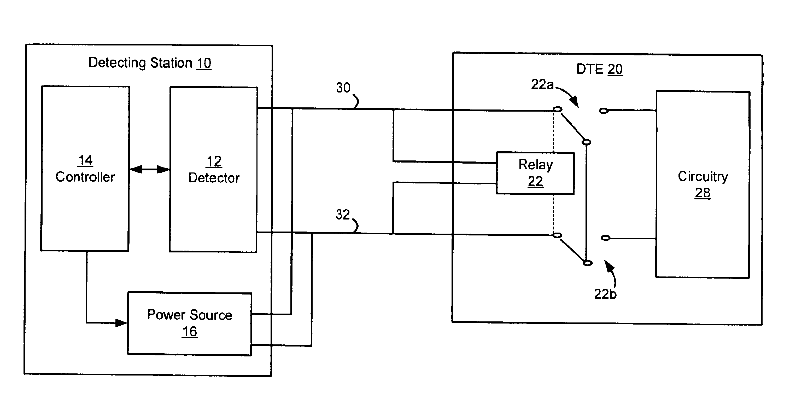
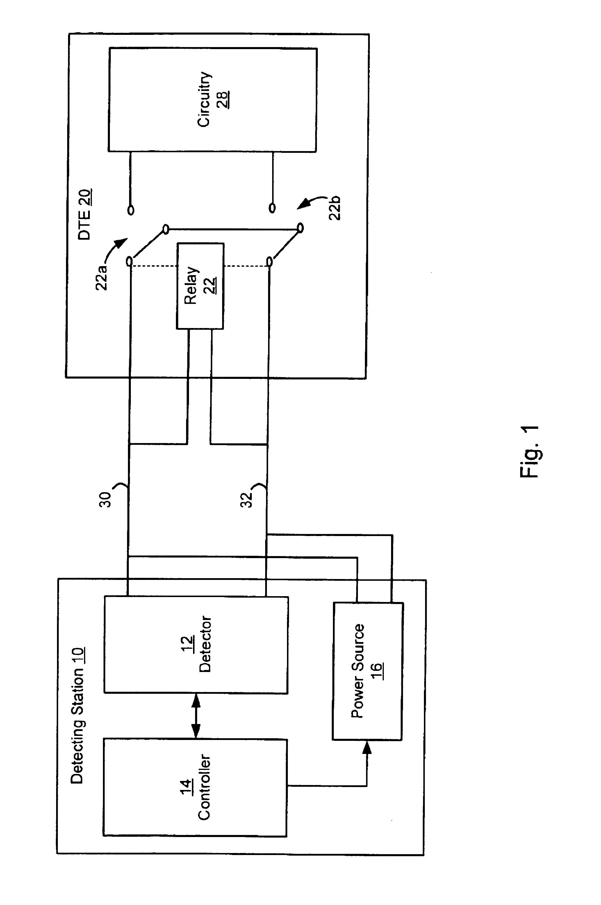
[0018]In accordance with a preferred embodiment of the present invention, a detector is utilized to detect the presence of device on a transmission line and whether the device requires power. The device can be data terminal equipment (DTE) or any other device that may require power. Exemplary DTE equipment includes any kind of computer, such as notebooks, servers, and laptops; smart VCRs, refrigerators, or any household equipment that could become a smart device; IP telephones, fax machines, modems, televisions, stereos, hand-held devices, or any other conventional equipment requiring power. If the presence of a DTE requiring power is detected, then the detector can supply power to the DTE.

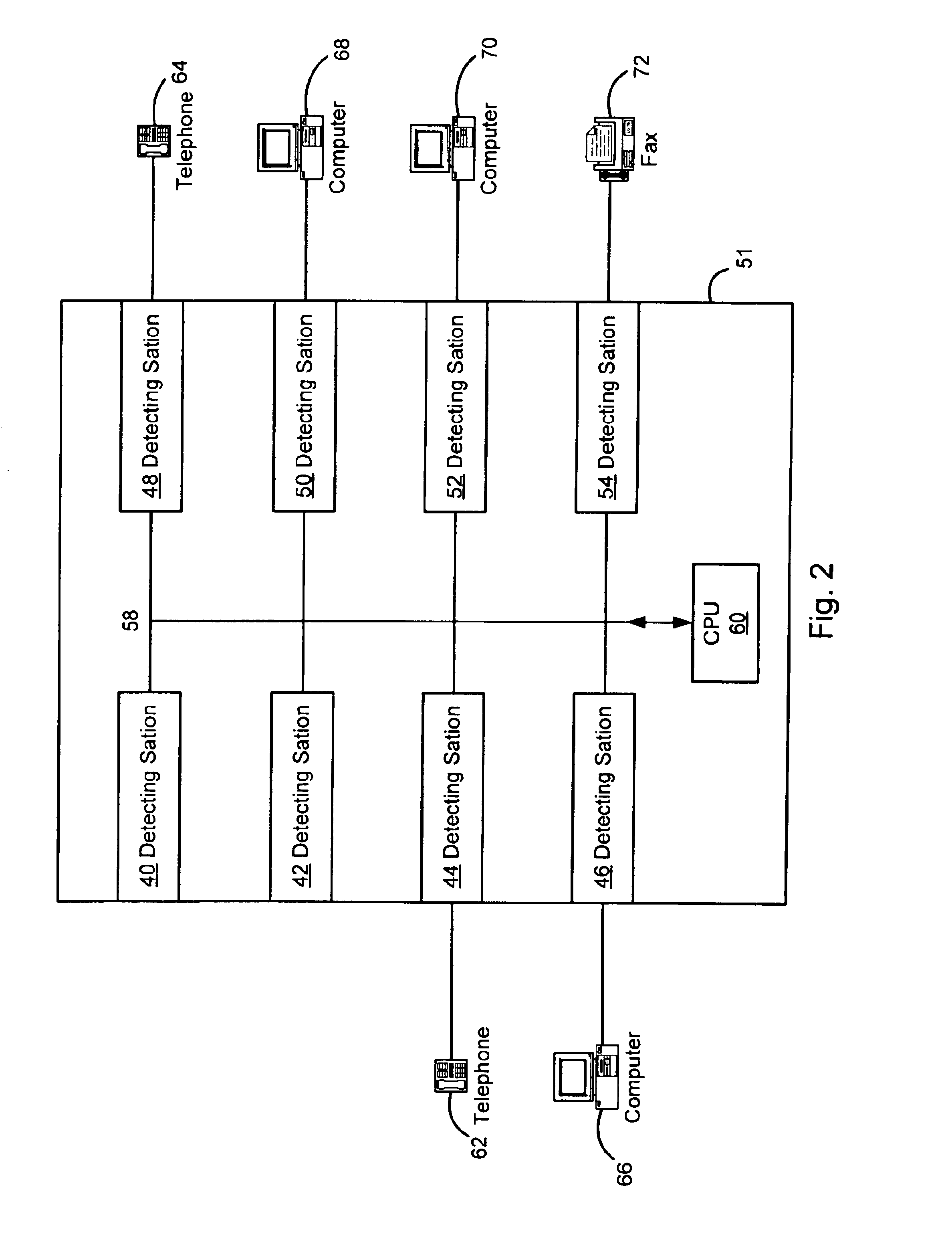
[0019]The described embodiment has broad applications. For example, a number of areas can benefit from power delivery over a transmission line including IP Telephony, Web Cameras, Wireless Access Points, Industrial Automation, Home Automation, Security Access Control and Monitoring Systems, Point ...


PUM


Abstract

A system and technique for detecting a device that requires power is implemented with a power detection station. The power detection system includes a detector having an output and a return which are coupled together by the device when the device requires power. The detector includes a word generator for generating test pulses for transmission to the device via the detector output, and a comparator for comparing the detector output with the detector return. The power detection station has a wide variety of applications, including by way of example, a switch or hub.

Description

CROSS-REFERENCE TO RELATED APPLICATIONS[0001]This patent application is a divisional of U.S. patent application Ser. No. 09 / 487,738, filed Jan. 19, 2000 now U.S. Pat. No. 6,571,181, entitled “System and Method for Detecting a Device Requiring Power,” which claims priority from provisional patent application 60 / 148,363, filed Aug. 11, 1999, both of which are hereby expressly incorporated herein by reference.FIELD OF THE INVENTION[0002]The present invention relates generally to telecommunications systems, and more particularly, to systems and techniques for detecting a device that requires power.BACKGROUND OF THE INVENTION[0003]Data terminal equipment (DTE) devices are well known. Examples of DTE devices include any kind of computer, such as notebooks, servers, and laptops; smart VCRs, refrigerators, or any household equipment that could become a smart device; IP telephones, fax machines, modems, televisions, stereos, hand-held devices, or any other conventional equipment requiring po...

Claims


Application Information

Patent Timeline
Patent Type & Authority Patents(United States)
IPC IPC(8): H04L12/10H04B1/69H04L12/26
CPCG06F1/266H02J13/0048H04L1/242H04L12/10H04L12/2697H04L43/50H04L25/02Y04S40/168H04L43/0817Y02B90/226Y04S20/16H02J13/00017H02J13/0001H02J13/0005Y04S40/00H02J13/00009Y02B90/20Y04S20/00
Inventor RAKSHANI, VAFAYOUSEFI, NARIMAN
Owner AVAGO TECH INT SALES PTE LTD
Why Eureka
Try Eureka