Method for receiver delay detection and latency minimization for a source synchronous wave pipelined interface

Inactive Publication Date: 2005-10-11
IBM CORP
View PDF6 Cites 12 Cited by
  • Summary
  • Abstract
  • Description
  • Claims
  • Application Information

AI Technical Summary

Benefits of technology

[0007]For digital systems having a self aligning interface the invention provides a method which enables the detection of delay for an synchrono

Problems solved by technology

Therefore, the target cycle setting usually adds extra latency and has a danger of violating the rec

Method used


Image

  • Method for receiver delay detection and latency minimization for a source synchronous wave pipelined interface
  • Method for receiver delay detection and latency minimization for a source synchronous wave pipelined interface
  • Method for receiver delay detection and latency minimization for a source synchronous wave pipelined interface

Examples


Embodiment Construction

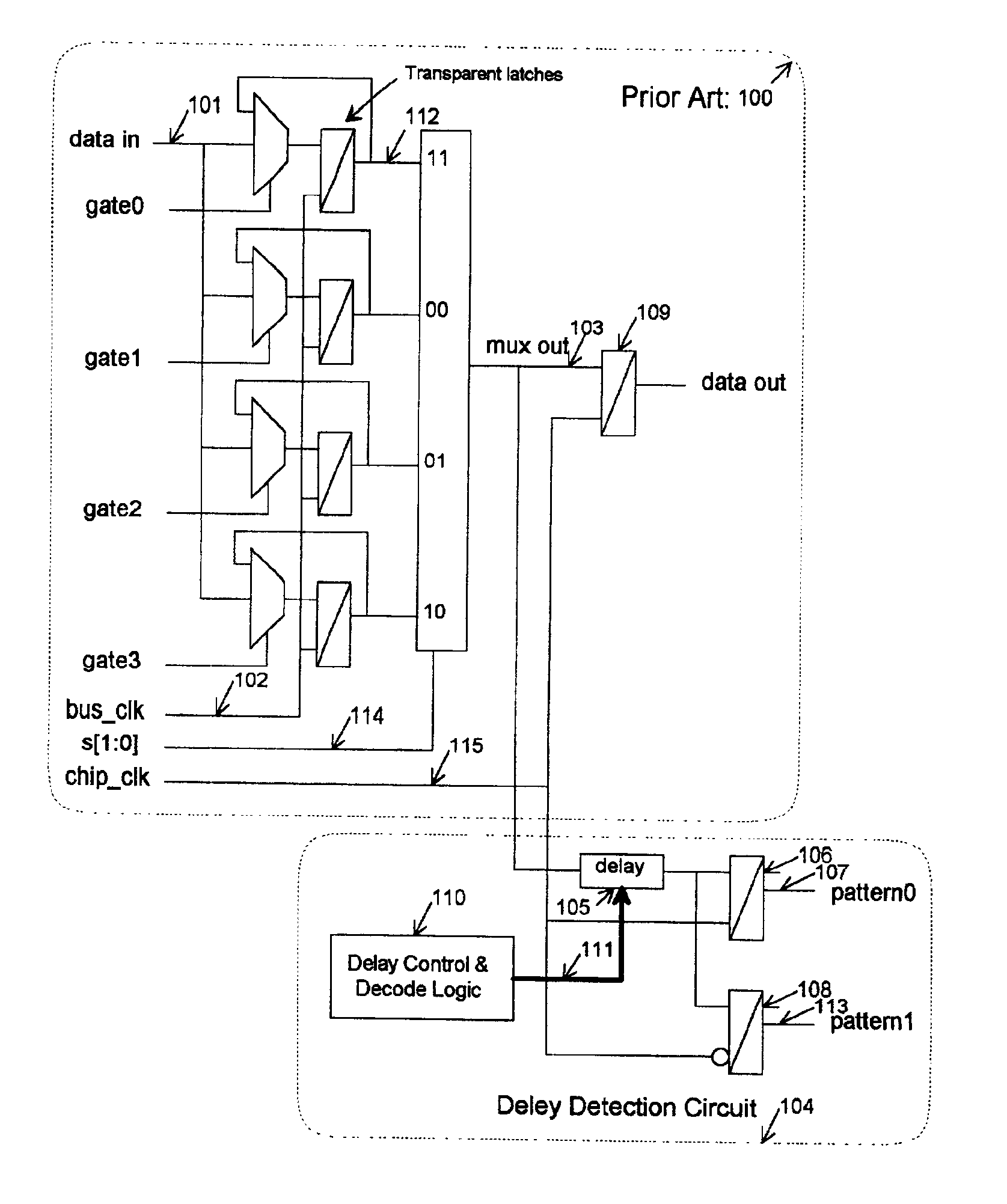
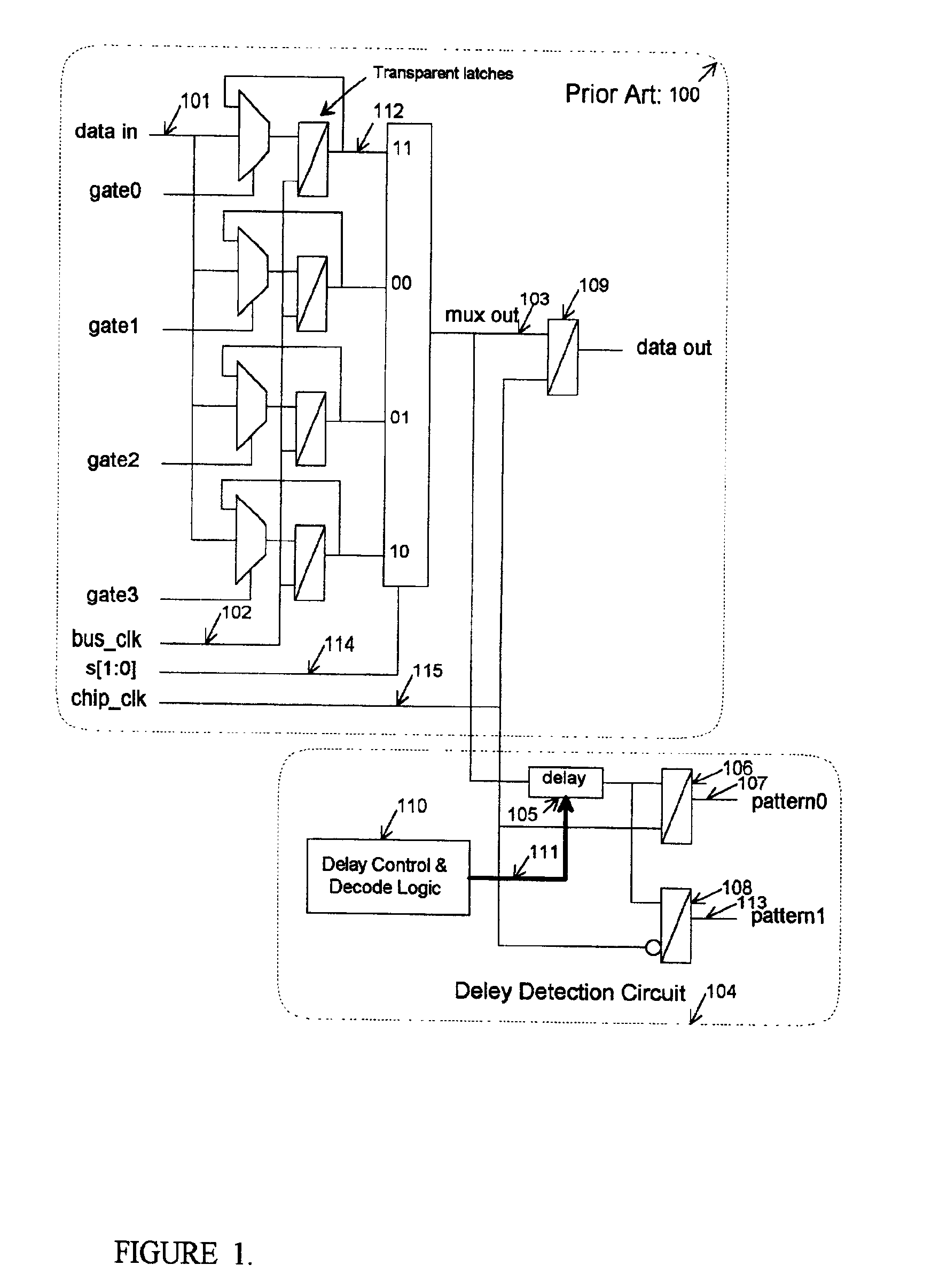
[0020]The Synchronous Wave Pipelined interface (a.k.a. Elastic interface) receivers must be calibrated first. During the calibration, the driver chip sends an known alignment pattern and the data bits of the receiver chip are delayed by the digital delay lines (See U.S. Pat. No. 6,285,229 Sep. 04, 2001 “Digital Delay Line with Low Insertion Delay” for an example which is incorporated herein by this reference) to align them with the latest data bit. The differential bus clock from the driver chip is also delayed by another digital delay line to force it to be ½ of the bus clock pulse width later than the data bits. The prior art Elastic interface receiver circuit 100 (enclosed by the dashed lines) as shown by FIG. 1 is for one data bit. This receiver circuit is connected to the data bit digital delay line output signal data in 101. The delayed bus clock (bus_clk) 102 is derived from the output of the clock digital delay line. The receiver circuit 100 is identical for all the data bit...


PUM


Abstract

A method of calibrating an elastic interface is provided to automatically achieve a minimal cycle delay through the interface. An existing self-alignment interface (i.e. elastic interface) is used to de-skew within a cycle and stage the data to have it arrive on a given, programmed target cycle. However, this target cycle must be calculated in advance and may be larger than it needs to be, causing more latency on the interface. This method is used to determine the earliest target cycle (with or without additional guard-band). This target cycle is used to adjust the interface automatically to achieve this earliest target cycle. The determination of earliest target cycle can be done once, continuously, or using a sample window. The method also can be used for interfaces that have frequency multipliers or phase shifts at its boundaries.

Description

FIELD OF THE INVENTION[0001]This invention relates to computers and other digital systems, and particularly to a method for use in a digital system having a self aligning interface which enables the detection of delay for an synchronous wave-pipelined interface between two integrated circuits chips and the receiver chip which is automatically adjusted to minimize the latency.RELATED APPLICATIONS[0002]These co-pending applications and the present application are owned by one and the same assignee, International Business Machines Corporation of Armonk, N.Y.: U.S. patent application Ser. No. 09 / 263,662 entitled “Dynamic Wave Pipelined Interface Apparatus and Method Therefor”.[0003]The descriptions set forth in these co-pending applications are hereby incorporated into the present application by this reference.[0004]Trademarks: z / 900 and S / 390 and IBM are trademarks of International Business Machines Corporation, Armonk, N.Y., U.S.A. Other names may be also be registered trademarks or p...

Claims


Application Information

Patent Timeline
IPC IPC(8): G06F3/00G06F1/12H04L7/00H04L7/10
CPCH04L7/005H04L7/10H04L7/0008
Inventor CHEN, JONATHAN Y.FERRAIOLO, FRANK D.GOWER, KEVIN C.MEANEY, PATRICK J.SCARPERO, JR., WILLIAM J.
Owner IBM CORP
Why Eureka
Try Eureka