Trencher guidance via GPS

a technology of gps and trenching equipment, which is applied in the direction of vehicle position/course/altitude control, process and machine control, instruments, etc., can solve the problems of affecting the operation of trenching, affecting the accuracy of trenching operations, and changing the location of the cutting edge of the digging implemen

Active Publication Date: 2005-10-18
TRIMBLE NAVIGATION LTD
View PDF3 Cites 63 Cited by
  • Summary
  • Abstract
  • Description
  • Claims
  • Application Information

AI Technical Summary

Benefits of technology

[0004]It is against the above background that the present invention provides a number of advantages and advances over the prior art. In particular, the present invention

Problems solved by technology

However, the location of the cutting edge of the digging implement is changing constantly during trenching operations.
As the pitch of the digging implement changes with digging depth, the mast angle of the laser receiver mounted above the cutting edge is changing similarly, thereby causing inaccurate measurements of the

Method used


Image

  • Trencher guidance via GPS
  • Trencher guidance via GPS
  • Trencher guidance via GPS

Examples


Embodiment Construction

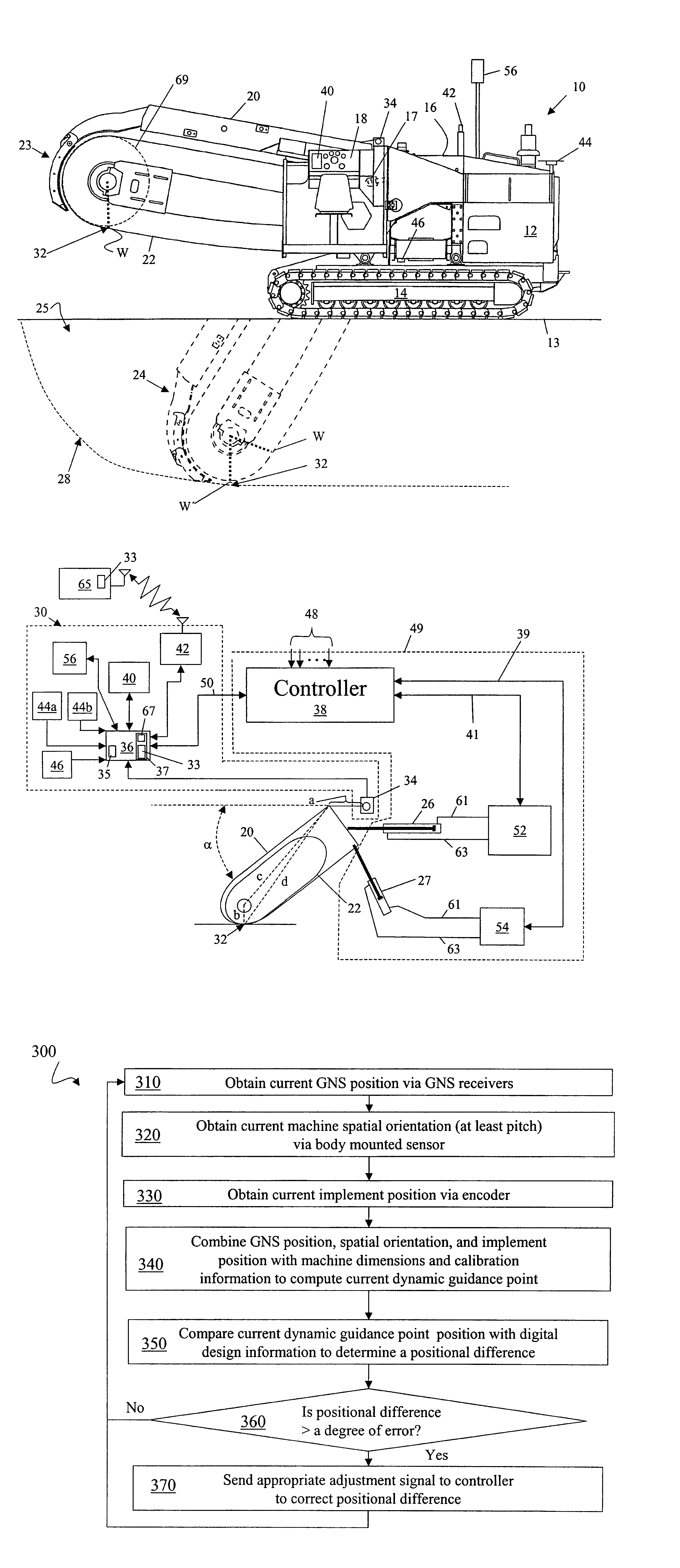
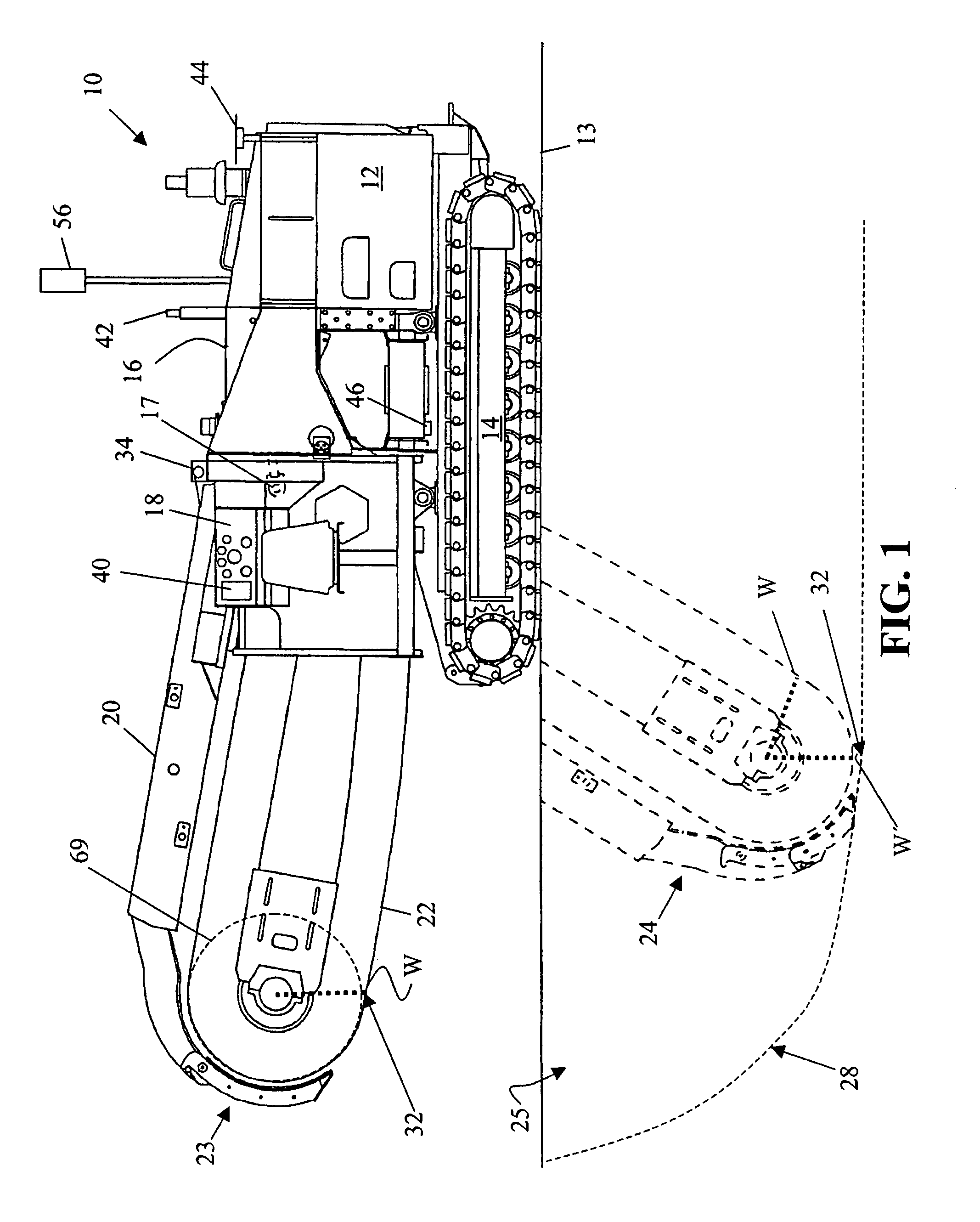
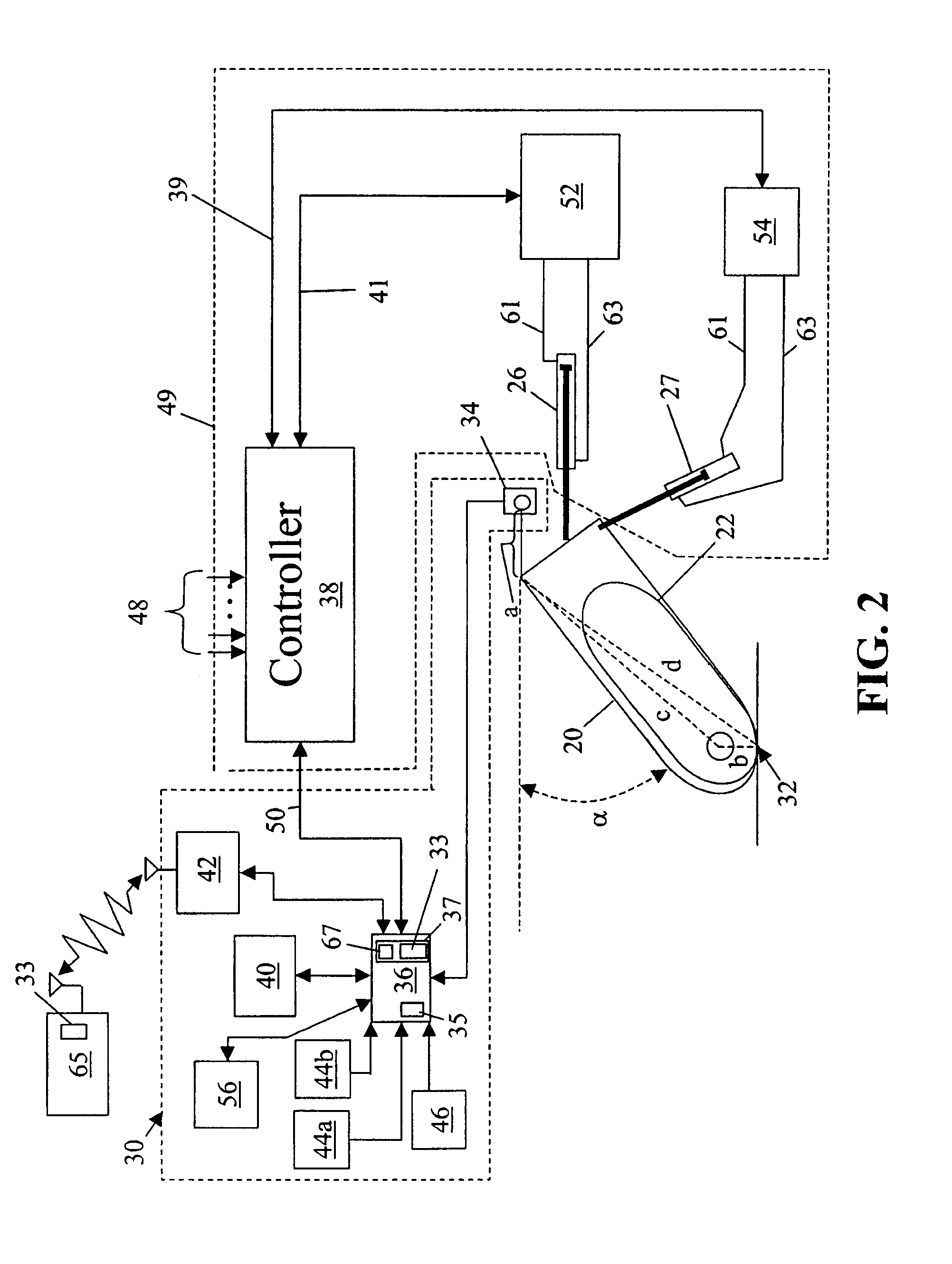
[0011]Although the present invention is herein described in terms of the illustrated embodiment, it will be readily apparent to those skilled in the art that various modifications, re-arrangements, and substitutions can be made without departing from the spirit of the invention. The present control system is described particularly herein with regard to working a subsurface of earth with a trencher, for example, to a desired shape and grade. However, this is for exemplary purposes only, and the present invention is not intended to be so limited. The present control system may be used in any suitable trenching machine or method to manually or automatically control the positioning of a cutting edge of its digging implement.

[0012]Referring now to the figures, and more particularly to FIG. 1, there is shown an illustration of one embodiment of a track trencher 10 well-suited for incorporating a novel guidance control system according to the present invention. The track trencher 10 typica...


PUM


Abstract

A guidance control system is configured to control the positioning and spatial orientation of a digging implement mounted on a frame of an trenching machine for working a subsurface of earth to a desired trench profile. The position of a dynamic cutting edge of the digging implement is monitored and then controlled so that the sensed dynamic cutting edge position is equal substantially to the calculated dynamic cutting edge position. The guidance control system includes sensors, a processor, and accessible memory providing digital design information regarding the desired trench profile.

Description

BACKGROUND OF THE INVENTION[0001]The present invention relates generally to control systems for controlling an implement carried by a machine, and more particularly, to a method and apparatus for controlling a digging implement of a trenching machine while trenching a subsurface of earth.[0002]Trenching machines for trenching the subsurface of earth at a construction site typically include a drive unit mounting some form of a trenching or digging implement, such as a digging chain or rock wheel. When preparing the subsurface of earth for, for example, a drain, a sewer, utility pipes, a cableway and the like, it is typically desirable for the contour or grade of the subsurface shaped by the digging implement to approximate a desired finished surface as closely as possible. How accurately the subsurface of earth is shaped depends upon both how accurately the position of a cutting edge of the digging implement can be determined and maintained, and how accurately the direction of travel...

Claims


Application Information

Patent Timeline
IPC IPC(8): E02F5/02G05D1/02G05D1/00G05D1/04E02F5/14E02F9/20
CPCE02F5/02E02F5/145E02F9/2045G05D1/0278G05D2201/0202
Inventor RICHARDSON, CHRISTOPHER D.LASHER, VINCENT LANSINGBEEKMAN, ROBERT MARVIN
Owner TRIMBLE NAVIGATION LTD
Why Eureka
Try Eureka