Inclining and rotating table apparatus

a technology of rotating table and inclining, which is applied in the direction of mechanical equipment, manufacturing tools, and gearing, etc., can solve the problems of inability to ensure the degree of precision of the inclining table, the difficulty of meeting such requirements with the precision that can be realized by conventional tools, and the processing error of the processed components, etc., to achieve high precision in indexing

Active Publication Date: 2005-10-18
SANKYO SEISAKUSHO
View PDF13 Cites 40 Cited by
  • Summary
  • Abstract
  • Description
  • Claims
  • Application Information

AI Technical Summary

Benefits of technology

[0013]The present invention has been made in view of conventional problems, and an object thereof is to provide an inclining and rotating table apparatus that is capable of ensuring high precision in indexing the angle at which a table surface of a rotating table is inclined.

Problems solved by technology

Thus, it has become difficult to comply with such requirements with the precision that can be realized by conventional tools.
Particularly, with a device used for continuous processing of extremely complicated curved surfaces for an inclining and rotating table apparatus, for example, even a slight eccentricity or play in the rotating table holding the workpiece, as well as in a mechanism for making the rotating table incline, will cause somewhat of a processing error in the processed components.
Therefore, with the inclining and rotating table apparatus which is required an especially high process precision, there is a problem that, in addition to precision at which the rotating table is indexed, the mechanism that makes the rotating table incline also has to be ensured a high indexing precision.
Bearing structures could be major factors that render a rotating table and a mechanism for making the rotating table incline unable to ensure adequate degree of precision.
Thus, not only is high operational precision unobtainable, but also the position of gap (d) changes due to the shift in weight, thus causing abrasion between the output shaft (a) and the inner race (c) and resulting in a shortened life of the device.
When the rollers rotate on the bearing race surface (h), due to the recesses and the protrusions of the bearing race surface (h), excessive pressure is applied to some portions of the bearing race surface (h), while some rollers fail to contact the race surface, thus making the rotating accuracy of the rollers unstable and the rotation center unstable.
As a result, it is difficult for the device to operate with a high degree of precision.
Moreover, excessive pressure applied between the rollers (g) and the race surface (h) causes excessive wear that shortens the life of the device.
As a result, recesses and protrusions will appear on the race surface (h) of the inner race (c), thus causing the same problems as those in the above-mentioned 2.
These problems occur between the output shaft (a) and the inner race (c) of the bearing (b) assembled thereto.
Even when high precision type bearings which are thus commercially available are used, it is difficult to ensure high indexing precision of the table surface of the rotating table due to various factors.

Method used


Image

  • Inclining and rotating table apparatus
  • Inclining and rotating table apparatus
  • Inclining and rotating table apparatus

Examples


first embodiment

===First Embodiment===

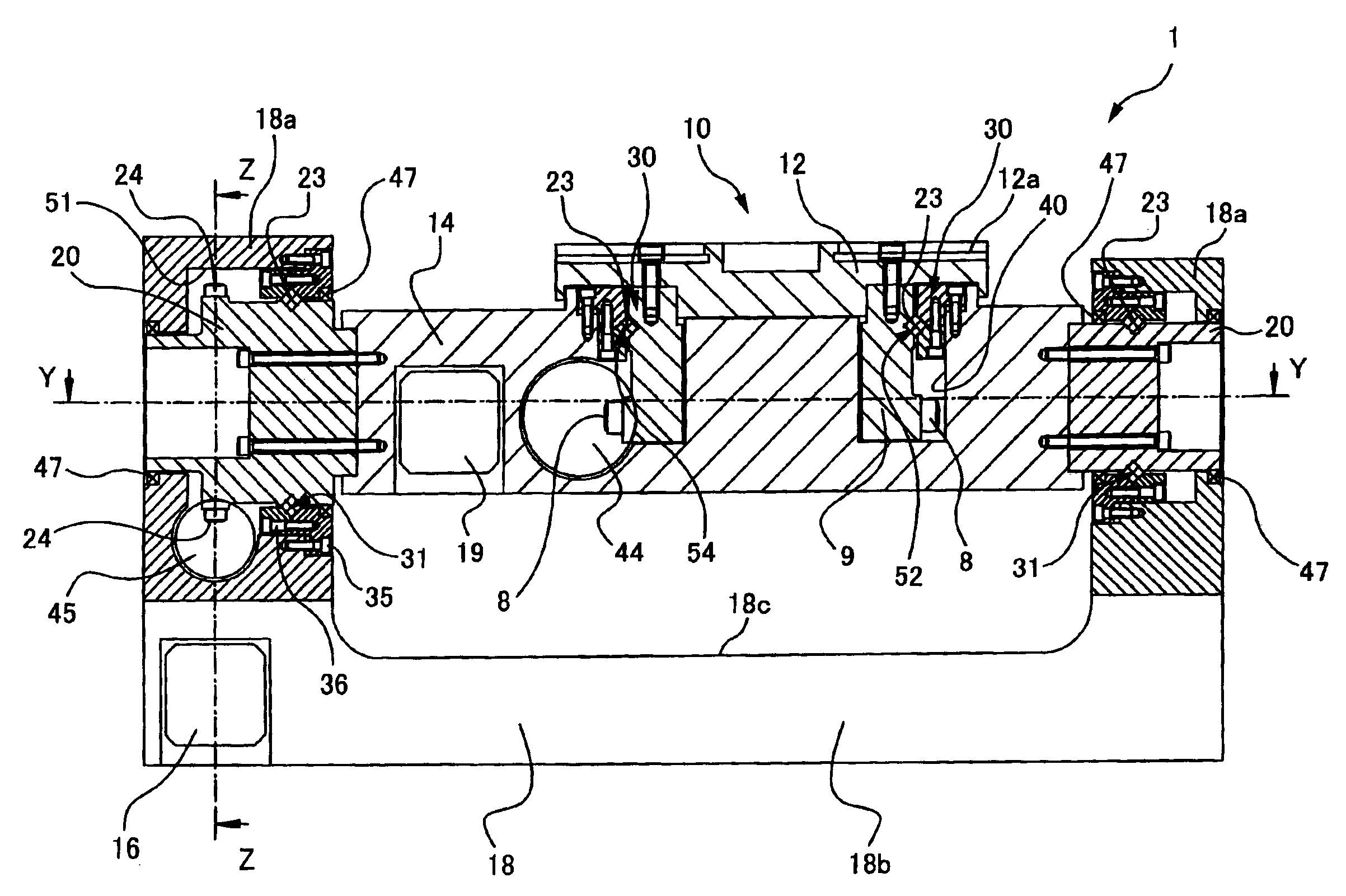
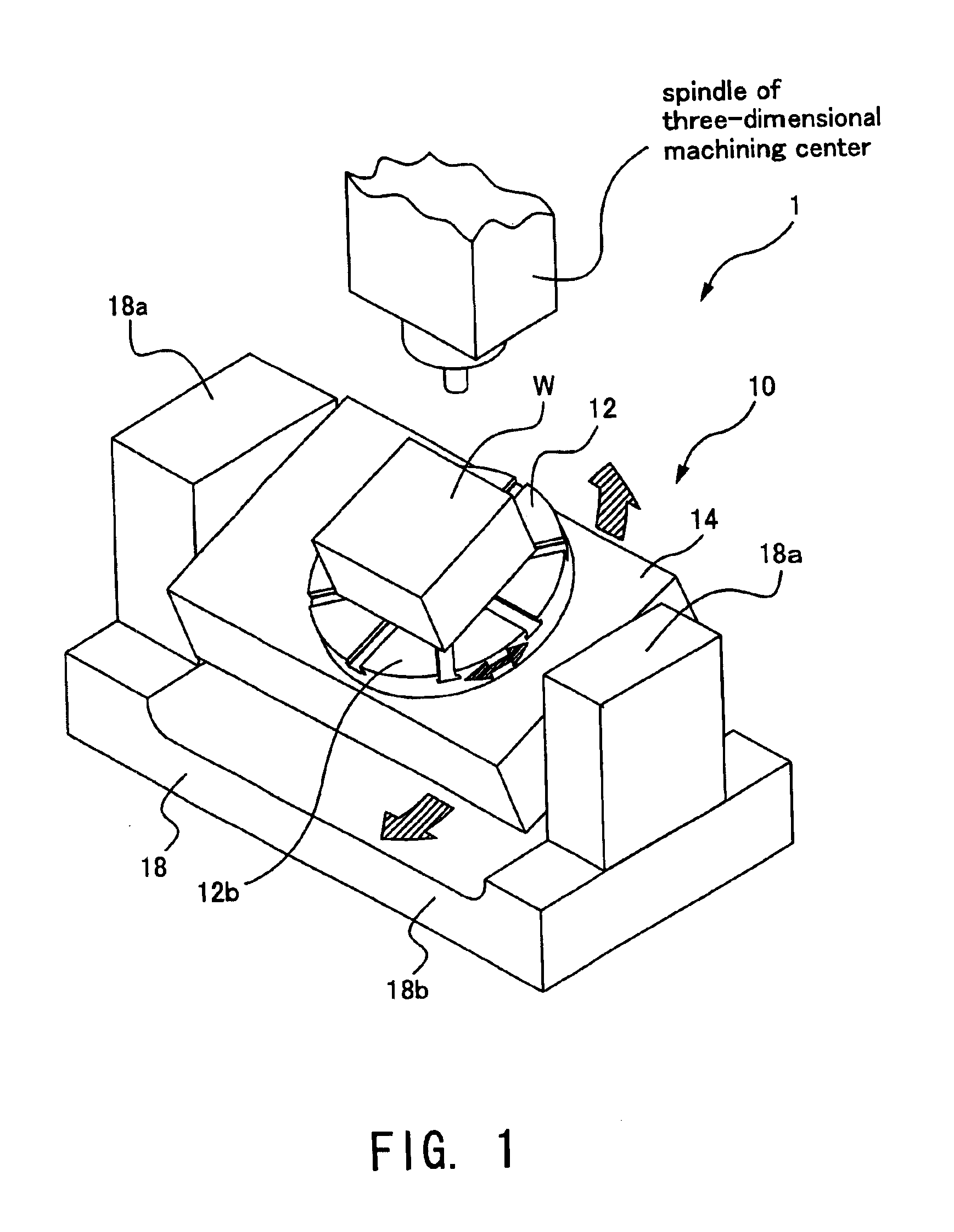
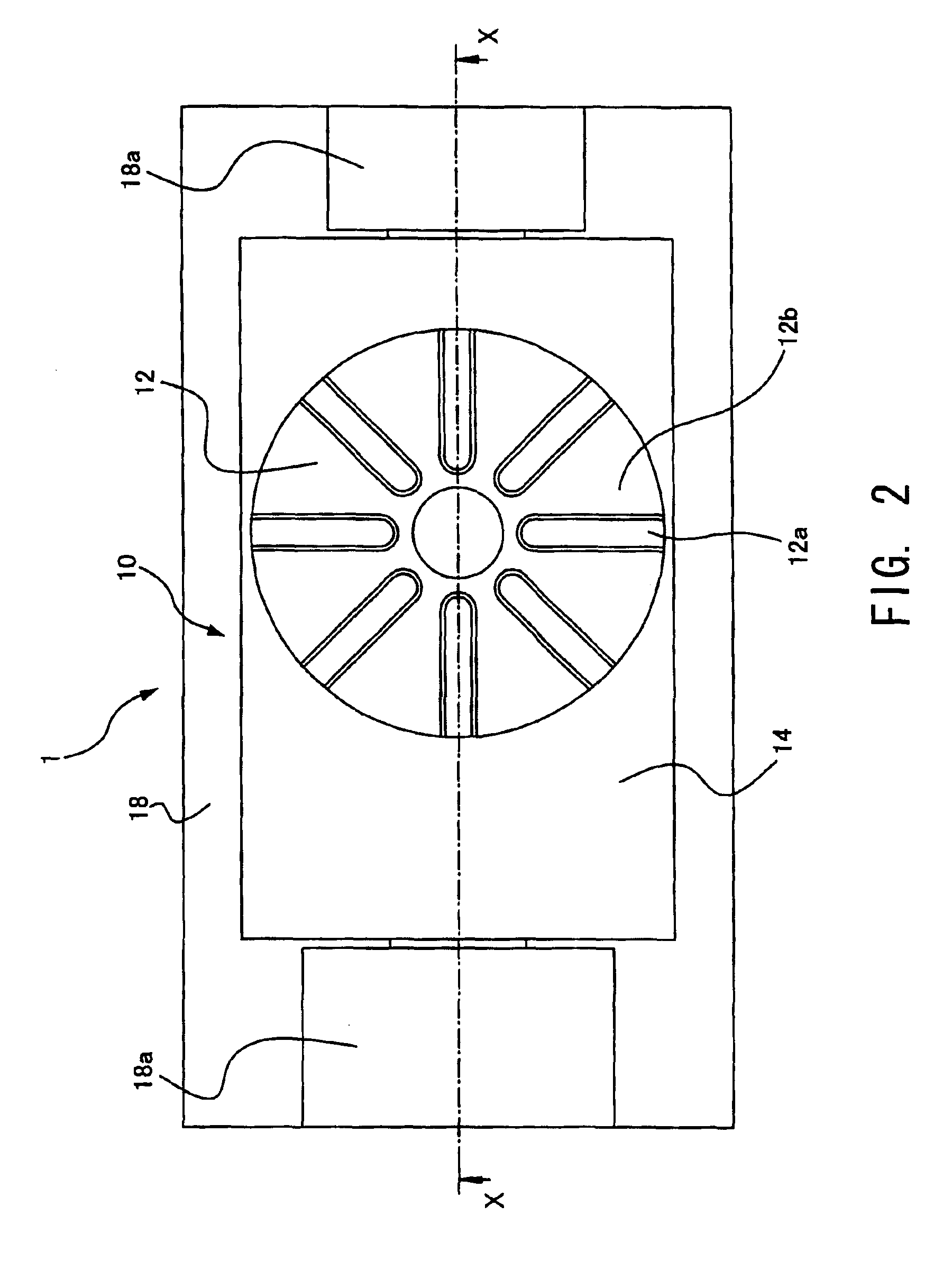
[0069]Hereinbelow, the first embodiment of the present invention will be explained in detail with reference to the attached drawings. FIG. 1 through FIG. 6 depict an embodiment of an inclining and rotating table apparatus of the present invention. FIG. 1 is a perspective view of an embodiment of the inclining and rotating table apparatus of the present invention, FIG. 2 is a plan view of the inclining and rotating table apparatus shown in FIG. 1, FIG. 3 is a front view of the inclining and rotating table apparatus shown in FIG. 1, FIG. 4 is a cross sectional view of FIG. 2 taken along line X—X, FIG. 5 is a cross sectional view of FIG. 4 taken along line Y—Y, and FIG. 6 is a cross sectional view of FIG. 4 taken along line Z—Z.

[0070]The inclining and rotating table apparatus 1 of this embodiment comprises, for example: a rotating table device 10 that comprises a rotating table 12 as a rotating table that rotates while holding a workpiece that is processed by, for...

second embodiment

===Second Embodiment===

[0101]Hereinbelow, the second embodiment of the present invention will be explained in detail with reference to the attached drawings. FIG. 16 through FIG. 20 depict a second embodiment of an inclining and rotating table apparatus of the present invention. FIG. 16 is a plan view of an inclining and rotating table apparatus according to the second embodiment, FIG. 17 is a front view of the inclining and rotating table apparatus according to the second embodiment, FIG. 18 is a cross sectional view of FIG. 16 taken long line X—X, FIG. 19 is a cross sectional view of FIG. 18 taken long line Y—Y, and FIG. 20 is a cross sectional view of FIG. 18 taken along line Z—Z.

[0102]The inclining and rotating table apparatus 101 of the second embodiment also comprises, for example: a rotating table device 110 that comprises a rotating table 112 as a rotating table that rotates while holding a workpiece that is processed by, for example, a three-dimensional machining center, an...


PUM

PropertyMeasurementUnit
rotationaaaaaaaaaa
circumferenceaaaaaaaaaa
poweraaaaaaaaaa

Abstract

An inclining and rotating table apparatus comprises a rotating table device having a rotating table, and a support base for rotatably supporting the rotating table having a shaft body provided perpendicular to a rotation axis of the rotating table, and a base for rotatably supporting the rotating table device using the shaft body. A table surface of the rotating table is inclined by making the rotating table device rotate. A first V-shaped groove is directly formed in the shaft body along its rotating direction. The base has a second V-shaped groove opposing the first V-shaped groove. A cross roller bearing is structured by providing rolling bodies, which are placed in contact with the first and second V-shaped grooves and are capable of rolling therebetween, between the shaft body and the base, and arranging a rolling axis of a rolling body perpendicular to that of an adjacent rolling body.

Description

CROSS-REFERENCE TO RELATED APPLICATIONS[0001]The present application claims priority upon Japanese Patent Application No. 2002-307297 filed Oct. 22, 2002 and Japanese Patent Application No. 2003-328855 filed Sep. 19, 2003, which are herein incorporated by reference.BACKGROUND OF THE INVENTION[0002]1. Field of the Invention[0003]The present invention relates to an inclining and rotating table apparatus for making a table surface of a rotating table incline by rotating a rotating table device having the rotating table rotatably supported by a support base.[0004]2. Description of the Related Art[0005]As an inclining and rotating table apparatus for making a table surface of a rotating table incline by rotating a rotating table device, there is known, for example, an inclined indexing round table which is attached on a work table of a machine tool such as a machining center (for example, refer to page 4 and FIG. 1 of Japanese Patent Application Laid-open Publication No. 2001-269829). Wi...

Claims


Application Information

Patent Timeline
Patent Type & Authority Patents(United States)
IPC IPC(8): B23Q1/25B23Q3/02B23Q3/04B23Q16/00B23Q1/50B23Q1/54B23Q16/10B23Q16/06B23D7/00B23D7/08B23Q1/26B23Q1/40B23Q3/06B23Q3/18F16C33/58F16H25/06F16H25/00F16C19/38F16C19/22B23Q1/00B23Q7/02
CPCB23Q1/5437B23Q16/102B23Q16/065Y10T409/30868B23Q7/02
Inventor KATO, HEIZABURO
Owner SANKYO SEISAKUSHO
Why Eureka
Try Eureka